22
Z6AM
HBM
A1559-2.0 de/en/fr
5
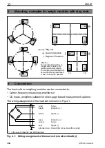
Mounting examples for weigh. modules with stay rods
Stay rod
Load introduction
Degree of freedom
120
°
120
°
120
°
90
°
90
°
90
°
90
°
Attention:
The represented bearing ar-
rangements consider only
weighing-technical criteria.
The carrying and stabilitymust
be examined and guaranteed
in each case by the operator.
6
Connection
The load cells on weighing modules can be connected to:
− Carrier-frequency measuring amplifiers or
− DC meas. amplifiers suitable for strain-gage based measurement systems.
The wiring assignment of the load cell is shown in Fig. 4.1.
(white)
Signal (+)
(black)
Excitation (−)
(gray)
Sense
(blue)
Excitation (+)
(green)
Sense
(red)
Signal (−)
(stranded wire) Shield, filler connected with housing*)
*) in the case of type Z6F and Z6G load cells
Fig. 4.1:
Wiring assignment of the load cell (six
-wire circuitry)
Summary of Contents for Z6AM
Page 2: ...Deutsch Seite 3 14 English Page 15 26 Fran ais Page 27 38...
Page 39: ......


