background image

34

Vedpak 177_Version 2_061013

171850 - 171853

171909 - 171914

NOTA: 

  Dopo l’installazione, ispezionare regolarmente la barra luminosa e i piedini di montaggio 


per verificare che tutti i dispositivi di fissaggio e le staffe siano ben serrate.

L’installazione include il centraggio e la messa in piano della barra luminosa sul tetto dei veicolo, nonché la 

marcatura a la trapanatura dei fori per il montaggio permanente della barra luminosa sul tetto.

1.  Posizionare la barra luminosa sul tetto del veicolo nella posizione desiderata. La barra luminosa è 


solitamente centrata sul montante centrale della portiera (montante B)

2.   Regolare entrambi i piedini di montaggio verso l’interno o verso l’esterno secondo necessità, per 


fare sì che i tamponi dei piedini poggino in prossimità del bordo del tetto o del canale, dove il tetto è 


più rigido. Verificare che la barra luminosa e i piedini di montaggio siano centrati da sinistra a destra 


sul veicolo.

3.   Mettere in piano la barra luminosa spostandola leggermente in avanti o all’indietro.

4.   Utilizzando i piedini di supporto come modello, marcare la posizione dei due fori da trapanare sul 


tetto del veicolo.

5.   Rimuovere con attenzione la barra luminosa e capovolgerla, quindi verificare che i piedini di supporto


non cambino posizione.

6.   Serrare i dadi che fissano i piedini di supporto alla barra luminosa.

7.   Ricavare quattro fori in corrispondenza delle posizioni precedentemente marcate.

ATTENZIONE: NON TRAPANARE la superficie di supporto del tetto che va dal 

lato del conducente a    


  quello del passeggero. Trapanando quest’area si indebolirebbe il tetto del veicolo.

NOTA:


  Prima di trapanare i fori, verificare che i fori attraversino il metallo della lamiera e non la 


  tappezzeria. Verificare inoltre che non vengano danneggiati componenti del veicolo.

8.   Posizionare la barra luminosa sul tetto del veicolo e allineare i fori di montaggio con i relativi piedini. 


Fissare i piedini di supporto al tetto del veicolo con gli appositi bulloni. L’installazione include il 


centraggio e la messa in piano della barra luminosa sul tetto dei veicolo, nonché la marcatura a la 


trapanatura dei fori per il montaggio permanente della barra luminosa sul tetto.

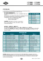
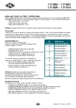
MONTAGGIO PERMANENTE 

BARRA LUMINOSA

PIEDINO DI MONTAGGIO

PIASTRA DI MONTAGGIO
BULLONE DI MONTAGGIO

TETTO DEL VEICOLO

Vista frontale della barra luminosa con montaggio permanente

Summary of Contents for 171850

Page 1: ...WCZA POD U NA LED LED LJUSRAMP LED LICHTBALKEN Mounting and Operation Instructions Installationsvejledning Einbauanleitung Betriebsanleitung Manuel d installation Manuale d installazione Instrukcja mo...

Page 2: ...bar the location to route the lightbar s Power Cable the location to route the Function Cable eg to siren switch box console WARNING Take extreme care when routing wires around airbag areas to not int...

Page 3: ...each end of the vehicle roof 5 Carefully remove the lightbar and turn it upside down and ensure that the mounting feet do not shift place 6 Tighten the nuts that secure the mounting feet to the light...

Page 4: ...t over the carriage bolts 3 Attach a lockwasher and a nut on each of the carriage bolts but do not completely tighten the bolts Leave them loose enough to reposition the mounting foot ADJUSTABLE FEET...

Page 5: ...a 40Amp fuse user supplied on the end of RED wire then connect to battery or power source 6 Splice the 2 BLACK wires to form a single wire 7 Connect BLACK wire to the factory chassis ground adjacent t...

Page 6: ...6 Single Split front only Outside In Single Outside In Single 7 Double Split front only Outside In Quad Outside In Quad 8 Quad Split front only Single All Single All 9 Single Quad front only Double A...

Page 7: ...ds are properly config ured 7 Exit PROGRAM mode by quickly tapping VDC to PURPLE wire 3 times within 1 second FP Lighthead Patterns 0 Steady 1 Single Slow split 2 Single Mid split 3 Single Fast split...

Page 8: ...for Left Arrow BLUE wire for Right Arrow ORANGE BLUE wires for Center Out To configure the Traffic Arrow flash patterns tap VDC to YELLOW wire Once for next pattern refer to Traffic Arrow Patterns cha...

Page 9: ...LED LYGTEBRO Installationsvejledning 171850 171853 171909 171914...

Page 10: ...l ledning skal tr kkes hvorhen funktionskablet skal tr kkes fx til sirene kontaktboks konsol ADVARSEL V r ekstremt forsigtig under ledningsf ringen ved airbags s deres korrekte funktion ikke p virkes...

Page 11: ...er i hver ende af k ret jets tag 5 Fjern forsigtigt lygtebroen og vend den p hovedet og s rg for at monteringsf dderne ikke flytter sig af stedet 6 Tilsp nd m trikkerne der fastg r monteringsf dderne...

Page 12: ...dderne over b reboltene 3 Fastg r en sp ndeskive og en m trik p hver af b reboltene men stram ikke boltene fuldst ndigt Lad dem sidde l st nok til at kunne rykke monteringsf dderne p plads JUSTERBARE...

Page 13: ...e TDere passage lys Afbrydelse front Afbrydelse bag Programming Ingen funktion Funktionerne aktiveres ved p f ring af VDC p en kontrolledning LEDNINGSF RING FOR LYGTEBRO STR MKABEL STR MKABEL 1 Tr k s...

Page 14: ...bbelt 6 Enkelt spalte kun forud Udvendig ind enkelt Udvendig ind enkelt 7 Dobbelt spalte kun forud Udvendig ind firdobbelt Udvendig ind firdobbelt 8 Firdobbelt spalte kun forud Enkelt alle Enkelt alle...

Page 15: ...us ved hurtig at holde VDC mod den LILLA ledning 3 gange indenfor 1 sekund BM 0 Konstant 1 Enkelt Langsom skift 2 Enkelt Mellemhast skift 3 Enkelt Hurtig skift 4 Dobbelt skift 5 Dobbelt skift 6 Femdel...

Page 16: ...DC mod ORANGE ledning for venstre l belys BL ledning for h jre l belys ORANGE BL ledninger for fra midten og ud For at konfigurere blinkem nstrene for l belysene holdes VDC let mod GUL ledning n gang...

Page 17: ...LED LEUCHTBALKEN Einbauanleitung Betriebsanleitung 171850 171853 171909 171914...

Page 18: ...Leuchtbalken montiert werden soll die Kabelf hrung des Stromkabels die Kabelf hrung des Funktionskabels z B zu Hupe Schaltkasten Konsole WARNUNG Extrem sorgf ltig vorgehen wenn Kabel in der N he der A...

Page 19: ...lone benutzen 5 Vorsichtig den Leuchtbalken wieder hochheben und umdrehen dabei darauf achten dass sich die F e nicht verschieben 6 Die Muttern auf den Schrauben mit denen die F e am Leuchtbalken befe...

Page 20: ...die Befestigungsschrauben setzen 3 An jeder Schraube eine Unterlegscheibe und eine Mutter anbringen aber noch nicht fest anziehen Sie sollten so lose sein dass die F e nachjustiert werden k nnen VERS...

Page 21: ...terbrecher hinten Programmierung Keine Funktion Funktionen werden aktiviert wenn VDC an Steuerkabel anliegt VERDRAHTUNG LEUCHTBALKELN STROMKABEL 1 Das Stromkabel zur Batterie oder Stromquelle f hren 2...

Page 22: ...vorn Au en innen einmal Au en innen einmal 7 Doppelt geteilt nur vorn Au en innen viermal Au en innen viermal 8 Viermal geteilt nur vorn Einmal alle Einmal alle 9 Einmal viermal nur vorn Doppelt alle...

Page 23: ...VIOLETTE Kabel angetippt wird FP Leuchtenmuster 0 Dauernd 1 Einmal langsam geteilt 2 Einmal mittel geteilt 3 Einmal schnell geteilt 4 Doppelt geteilt 5 Doppelt geteilt 6 F nfmal geteilt 7 Ultra geteil...

Page 24: ...NGES und BLAUES Kabel f r beide Pfeile Um das Blinkmuster der Verkehrspfeile einzustellen kurz VDC an GELBES Kabel antippen Einmal f r das n chste Muster vgl bersicht der Blinkmuster der Verkehrspfeil...

Page 25: ...RAMPE LUMINEUSE LED Manuel d installation 171850 171853 171909 171914...

Page 26: ...tion de la rampe le chemin de passage des c bles des accessoires de la rampe p ex vers sir ne bo te d interrupteurs console AVERTISSEMENT Agir extr mement prudemment pour passer les c bles proximit de...

Page 27: ...de forage chaque extr mit du toit du v hicule 5 Retirer d licatement la rampe lumineuse et la retourner l envers en veillant ce que les pieds de montage ne se d placent pas 6 Resserrer les boulons qui...

Page 28: ...serie 3 Placer une rondelle de blocage et un crou sur chacun des boulons de carrosserie SFlb Ne pas serrer les crous compl tement Il faut pouvoir r ajuster la position du pied PIEDS R GLABLES Inverser...

Page 29: ...u fil ROUGE et connecter l autre extr mit la batterie ou l alimentation 6 Faire une pissure pour rassembler les 2 fils NOIRS en un seul 7 Raccorder le fil NOIR sur la masse de ch ssis d origine c t de...

Page 30: ...te c te quadr 6 Simple divis avant uniquement Ext rieur int simple Ext rieur int simple 7 Double divis avant uniquement Ext rieur int quadr Ext rieur int quadr 8 Quadr divis avant uniquement Simple to...

Page 31: ...IOLET N C Modes de projecteurs 0 Permanent 1 Simple lent divis Single Slow split 2 Simple moyen divis Single Mid split 3 Simple rapide divis Single Fast split 4 Double divis Double split 5 Double divi...

Page 32: ...che centrale Pour configurer les diff rents modes de clignotement des fl ches connecter le VCC au fil JAUNE une fois pour le mode de clignotement MC suivant voir les tableaux de mode de fl ches de tr...

Page 33: ...so la sirena la scatola interruttori o la consolle comandi ATTENZIONE Prestare la massima attenzione mentre si fanno passare i cavi attorno alla zona degli airbag per non interferire con il loro corre...

Page 34: ...la posizione dei due fori da trapanare sul tetto del veicolo 5 Rimuovere con attenzione la barra luminosa e capovolgerla quindi verificare che i piedini di supporto non cambino posizione 6 Serrare i d...

Page 35: ...a di blocco e un dado su ciascun bullone di supporto senza per serrarli completamente Lasciarli abbastanza lenti da consentire il riposizionamento del piedino di supporto SUPPORTO CON SUPERFICIE AMPIA...

Page 36: ...i collegare alla batteria o alla fonte di alimentazione 6 Giuntare i due cavi NERI in modo da formare un solo conduttore 7 Collegare il cavo nero al punto di collegamento a massa sul telaio adiacente...

Page 37: ...teriore Esterno Interno Singolo Esterno Interno Singolo 7 Doppio Suddiviso solo anteriore Esterno Interno A quattro Esterno Interno A quattro 8 A quattro suddiviso solo anteriore Singolo tutti Singolo...

Page 38: ...alit di PROGRAMMAZIONE applicando la tensione VDC sul filo VIOLA rapidamente 3 volte entro un secondo FP Modelli testine luminose 0 Stabile 1 Singolo lento suddiviso 2 Singolo medio suddiviso 3 Singol...

Page 39: ...per la freccia a sinistra il filo BLU per la freccia a destra i fili ARANCIONE BLU per centro esterno Per configurare il modello di lampeggio delle frecce traffico applicare la tensione VDC sul filo G...

Page 40: ...jsce poprowadzenia przewodu steruj cego np do syreny skrzynki rozdzielczej itp OSTRZE ENIE zachowaj szczeg ln ostro no je li przewody maj zosta poprowadzone w pobli u poduszek powietrznych pojazdu 4 O...

Page 41: ...ca na wywiercenie dw ch otwor w na obu ko cach dachu pojazdu 5 Ostro nie zdejmij belk obr j spodem do g ry i upewnij si e n ki monta owe nie przesun y si 6 Dokr nakr tki mocuj ce n ki monta owe do bel...

Page 42: ...ych 3 Za pier cie ustalaj cy i nakr tk na ka d ze rub no nych nie dokr caj c rub do oporu Pozostaw im nieco luzu aby dopasowa po o enie n ek monta owych MONTA NA DACHU POJAZDU Widok belki obr conej sp...

Page 43: ...ia 6 Skr dwa CZARNE przewody w pojedynczy przew d 7 Pod cz CZARNY przew d do przygotowanego okablowania w pobli u akumulatora UWAGA upewnij si e wszystkie y y przewodu zasilaj cego zosta y na trwa e p...

Page 44: ...zewn trz do rodka pojedynczo 7 Podw jne rozproszenie tylko prz d Na zewn trz poczw rnie Na zewn trz poczw rnie 8 Poczw rne rozproszenie tylko prz d Pojedynczo wszystkie Pojedynczo wszystkie 9 Pojedyn...

Page 45: ...i cia V DC do FIOLETOWEGO przewodu 3 razy w ci gu 1 sekundy PROGRAMOWANIE RESETOWANIE Przywracanie ustawie fabrycznych 1 Gdy przewody s niepod czone wybierz tryb RESETOWANIA poprzez przy o enie napi c...

Page 46: ...POMARA CZOWY i NIEBIESKI przew d w przypadku kierunkowskaz w dwustronnych Aby ustawi sekwencje migania kierunkowskaz w pod cz na chwil napi cie V DC do TEGO przewodu jeden raz aby wybra nast pn sekwen...

Page 47: ...r att dra kablarna till t ex siren styrbox konsol VARNING Var f rsiktig om kablar dras runt krockkuddar s att det inte orsakar funktionsproblem 4 Separera allt elektroniskt kablage fr n kablage tillh...

Page 48: ...p respektive sida av fordonets tak 5 Ta f rsiktigt bort ljusrampen och v nd den upp och ner se till att monteringsf tterna inte flyttas 6 Dra t muttrarna som h ller fast monteringsf tterna mot ljusra...

Page 49: ...upp och ner 2 Placera monteringsf tterna ver kl mskruvarna 3 F st en l sbricka och mutter p respektive kl mskruv men dra inte t skruvarna helt L t dessa vara l sa nog f r att justera in monteringsfote...

Page 50: ...kabeln anslut d refter till batteri eller str m k lla 6 Skarva de 2 SVARTA kablarna f r att bilda en kabel 7 Anslut SVART kabel till chassijordningspunkt i n rheten av batteriet OBS se till att alla e...

Page 51: ...n singel Utsida in singel 7 Dubbel delad endast fram Utsida in fyrdelad Utsida in fyrdelad 8 Fyrdelad endast fram Singel alla Singel alla 9 Singel fyra endast fram Dubbel alla Dubbel alla 10 Sida vid...

Page 52: ...LA kabeln 3 g nger inom 1 sekund FP Lampm nster 0 Fast 1 Singel l ngsamt delad 2 Singel mellan delad 3 Singel snabb delad 4 Dubbel delad 5 Dubbel delad 6 Femdelad delad 7 Ultra delad 8 Singel fyra del...

Page 53: ...ORANGE och BL kablar f r centrum och ut F r att st lla in trafikpilarnas blixtm nster l gger man en str mpuls p den GULA kabeln En g ng f r n sta m nster se listan ver trafikpilarnas m nster Snabbt 3...

Page 54: ...e plaats waar de functiekabel bijv naar sirene schakelkast console gelegd wordt WAARSCHUWING Wees zeer voorzichtig wanneer u kabels rond de gebieden van de airbags legt om verstoring van de functie te...

Page 55: ...e kant van het dak van het voertuig 5 Verwijder de lichtbalk voorzichtig en draai hem ondersteboven zorg ervoor dat de montagevoeten niet verschuift 6 Draai de moeren aan waarmee de montagevoeten aan...

Page 56: ...de montagevoeten over de slotbouten 3 Zet een borgring en een moer op elke slotbout maar draai de bouten niet helemaal aan Laat ze voldoende los om de montagevoeten te kunnen bewegen VERSTELBARE VOETE...

Page 57: ...inde van de RODE draad en sluit dan aan op accu of krachtbron 6 Splits de 2 ZWARTE draad om een enkele draad te vormen 7 Sluit de ZWARTE draad aan op de fabrieksaarding op het chassis naast de accu LE...

Page 58: ...binnen enkel Van buiten naar binnen enkel 7 Dubbel gesplitst alleen voor Van buiten naar binnen vierdubbel Van buiten naar binnen vierdubbel 8 Vierdubbel gesplitst alleen voor Enkel alles Enkel alles...

Page 59: ...binnen 1 seconde snel te drukken op VDC naar PAARSE draad FP Lamp patronen 0 Vast 1 Enkel langzaam gesplitst 2 Enkel medium gesplitst 3 Enkel snel gesplitst 4 Dubbel gesplitst 5 Dubbel gesplitst 6 Vi...

Page 60: ...ORANJE draad voor pijl links BLAUWE draad voor pijl rechts ORANJE BLAUWE draden voor vanuit midden naar buiten Om de flitspatronen van de verkeerspijlen te configureren drukt u op VDC naar GELE draad...

Reviews: