5
Vedpak 177_Version 2_061013
171850 - 171853
171909 - 171914
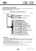
WIRING & FUNCTIONS
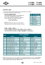
Different applications require different functions. It is highly recommended to determine and configure the
required functions prior to Installation; (refer to ‘CONTROL CABLE’ section).
POWER CABLE
1. Route Power Cable towards battery or power source.
2. Follow factory wiring harness through the firewall. It may be necessary to drill a hole in the firewall.
Ensure that there are no components that could be damaged from the drilling.
3. Route the cable to the battery.
4. Splice the 2 RED wires to form a single wire.
5. Install a 40Amp fuse (user-supplied) on the end of RED wire, then connect to battery or power source.
6. Splice the 2 BLACK wires to form a single wire.
7. Connect BLACK wire to the factory chassis ground adjacent to the battery.
NOTE:
make sure that all wires of power cable are securely connected to power source.
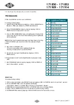
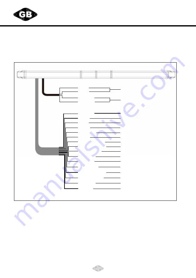
POWER CABLE
RED
BLACK
BROWN
PINK
RED
GREY
ORANGE
BLUE
BROWN - BLK
BLUE - BLK
YELLOW
GREEN
RED - BLK
YELLOW - BLK
GREEN - BLK
PURPLE
WHITE
RED
ORANGE - BLK
BLACK
To +VDC with 40A fuse
To chassis ground
ECE R65 Mode
Mode 1
Mode 2
Mode 3
Rear "Left Arrow"
Rear "Right Arrow"
Take Downs
Right-Side Alley Lights
Left-Side Alley Lights
Flash Pattern for LEDs & TD/Alley
DIM Mode
Flashing TDs & Alleys
Front cutoff
Rear cutoff
Programming
Option
Functions are activated by apVDC to a control wire.
LIGHTBAR WIRING


