6
Vedpak 177_Version 2_061013
171850 - 171853
171909 - 171914
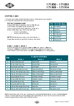
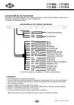
CONTROL CABLE
1. Route Control Cable towards the dash area to a switch panel (user-supplied).
2. Connect the required wires to the switch panel.
NOTE:
Flash Pattern #0 can be user customized by entering PROGRAM Mode, (refer to PROGRAMMING
section). All other patterns are still available after customization is done. There is a reset function which
restores original factory setting; refer to RESET section.
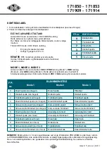
FP#
FLASH PATTERNS
Mode 1
Mode 2
Mode 3
0
Single Split (rear only)
Single Split
Random
1
Double Split (rear only)
Double Split
Double Split
2
Quad Split (rear only)
Quad Split
Quad Split
3
Single-Quad Split (rear only)
Single-Quad Split
Single-Quad Split
4
Side-by-Side Single (rear only)
Side-by-Side Single
Side-by-Side Single
5
Side-by-Side Quad (rear only)
Side-by-Side Quad
Side-by-Side Quad
6
Single Split (front only)
Outside-In Single
Outside-In Single
7
Double Split (front only)
Outside-In Quad
Outside-In Quad
8
Quad Split (front only)
Single All
Single All
9
Single-Quad (front only)
Double All
Double All
10
Side-by-Side Single (front only)
Quad All
Quad All
11
Side-by-Side Quad (front only)
Single-Quad All
Single-Quad All
ECE R65 WARNING MODE
Activate R65 Mode by apVDC to BROWN wire.
This activates the lightbar outter sections only.
There is a list of built-in flash patterns to choose from.
While in R65 Mode, tap +VDC to YELLOW wire:
•
Once for next pattern.
•
Quickly 3 times for FP#0.
NOTE
: R65 Mode has priority over all other Modes, 5
Single Split and will override other functions when active
MODE 1, MODE 2, MODE 3
Activate desired Mode by applying
+VDC
to
PINK
wire (Mode 1),
RED
wire
(Mode 2), or
GRAY
wire (Mode 3). This activates the lightbar according to the
Flash Patterns chart. While active, tap
+VDC
to
YELLOW
wire to change pattern.
FP# ECE R65 Mode
0
Double All
1
Quad All
2
Single All
3
Double Split
4
Quad Split
5
Single Split


