14
WARNING:
The Control will revert to Automatic operation after 10 minutes
following a Manual Maintenance Operation. The control will then automatically
Open or Close the capacitor bank based upon the Automatic Operation
programmed settings.
AUTOMATIC
OPERATIONS
For the following operations,
please reference the
Overview Section (pg. 4)
to see if the operation
pertains to your control.
Automatic Voltage Operation
–
Automatic Voltage Control Mode
is active when the front panel
rotary switch position is set to
AUTO, and the Control Mode is
set to VOLTAGE. The AUTO LED
will also light. When Automatic
Voltage Control Mode is active,
the control tests the Voltage
against the programmed Open
and Close settings. To adjust the
set points for automatic voltage
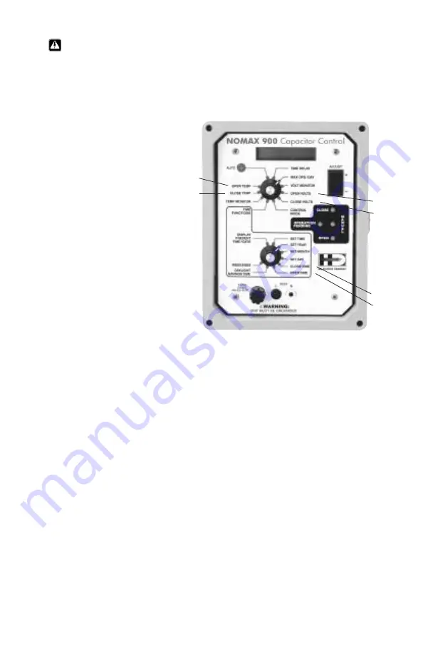
operation, use the front panel rotary switch to select the
parameter. Please refer to Figure 5.
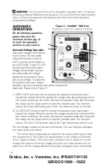
1) OPEN VOLTS is the set point for opening the capacitor bank based upon
sensed line voltage. When the sensed line voltage rises above this set point for
one minute continuous, the control will open the capacitor bank after the preset
time delay. Use the Adjust switch to select the desired value. The minimum
value is the Close Volts setting plus 3 volts. The maximum value is 130 volts.
2) CLOSE VOLTS is the set point for closing the capacitor bank based upon
sensed line voltage. When the sensed line voltage drops below this set point for
one minute continuous, the control will close the capacitor bank after the preset
time delay. Use the Adjust switch to select the desired value. The minimum
value is 105 volts. The maximum value is the Open Volts setting minus 3 volts.
The Line Voltage is tested at one-second intervals. The Line Voltage is averaged
over eight cycles per interval.
The control also incorporates an Adaptive Trip feature utilizing the Delta
Volt measurement. The Delta Volt measurement is the voltage contribution
of the Capacitor Bank. If the next close operation would cause the control
voltage to be above the open voltage set point, the close operation is not
performed until the voltage falls below the open voltage set point minus Delta
5
6
1
2
3
4
Figure 5 – NoMAX
®
900 Unit
Check your control for specific functions
Gridco, Inc. v. Varentec, Inc. IPR2017-01135
GRIDCO 1008 - 16/22


