3
1
2
4
a
b
d
c
Page 1 (1)
User manual /
Assembly instructions
Art. no.: 67115-5
MANUFACTURER: Hantverksdesign & Rehabiliteringsprodukter AB
Tryffelslingan 4, SE-181 57 Lidingö, Sweden
tel. +46 8 767 04 80
fax. +46 8 767 50 00
www.hdrehab.se info@hdrehab.se
Rev. A
Latest revision: 2011-12-15
Art.no. 95822-1
- Due to its extended length this brake is more fragile than the standard brake. In some cases
it can also interfere with the movement in and out of the wheelchair.
- Angle the legrests outwards with care to prevent the screw and knee joint from getting
damaged.
!
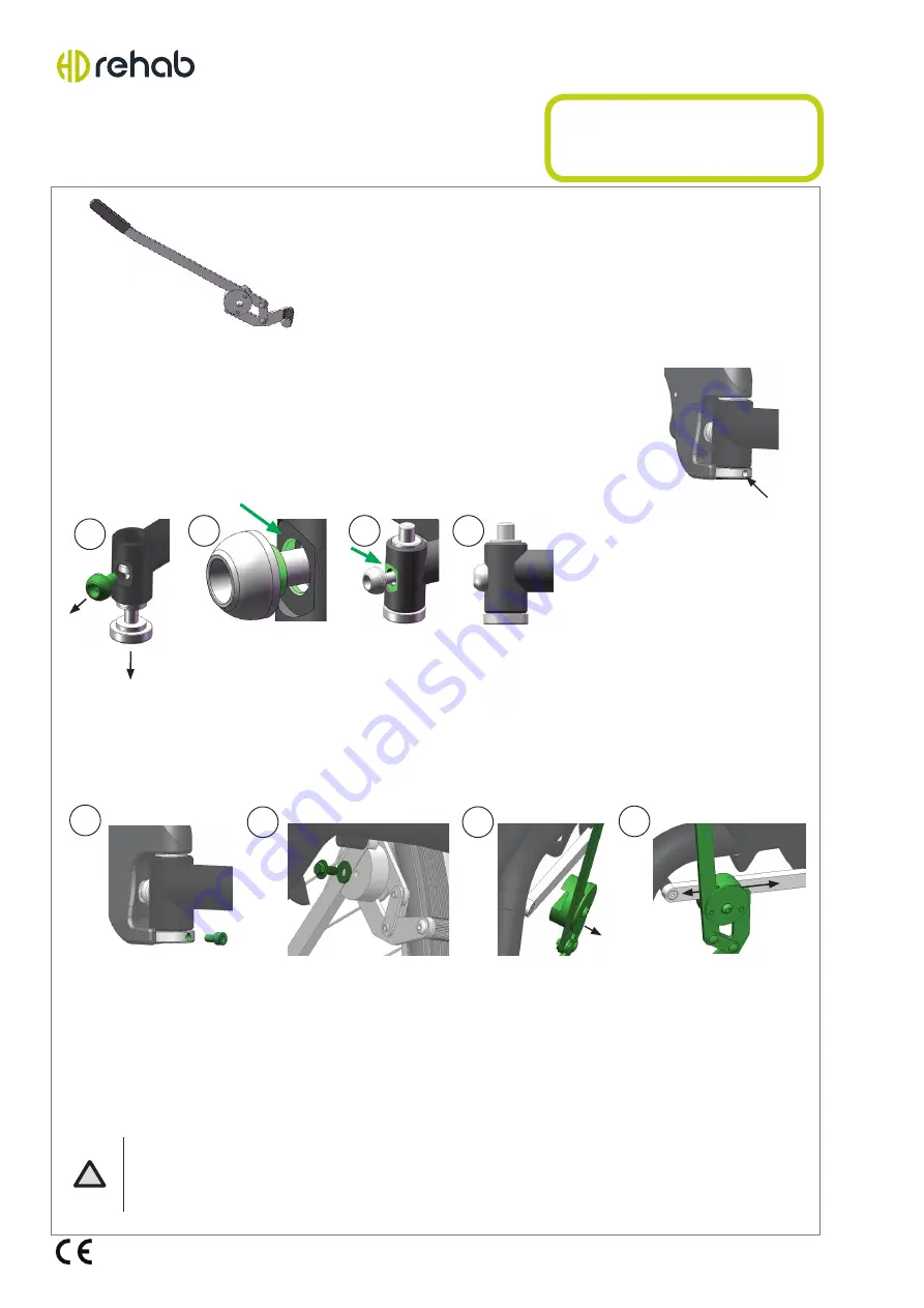
1. Mount the stop screw. Use threadlocker of type Loctite 2400.
2. Demount the existing brake by loosening the screw and washer.
3. Remove the brake from the brake bar.
Attatch the new brake the same way as the old one was mounted.
4. Adjust the brake performance by moving the brake along the
brake bar. Make sure that the brake performance is big enough
before tightening the screw.
Loosen the screw as shown and push the pin down (a). Note: The screw is tight
and a proper tool is needed. Replace the pin with the new one. Put threadlocker,
of type Loctite 2400, on the screw and then thread it gently by hand. Make sure
the guide part of the screw sets in the round seat (b). The screw must not get
skewed! When the screw head bears against the flat surface (c, d) the screw is
tightened rigorously with a key.
Note:
The assembling must only be performed by authorized personnel.
First check if the wheelchair is equipped with the newer version of the pin in the
legrest fastening. The pin must have a threaded hole (according to the image to
the right) in which a screw will be mounted. This prevents the legrest to collide
with the brake lever when angled outwards. If the hole is missing, the pin is
replaced with a pin with a hole (Contact HD Rehab for ordering). Mounting is as
follows:
Assembling
Extended brake lever
HD Balance 24"


