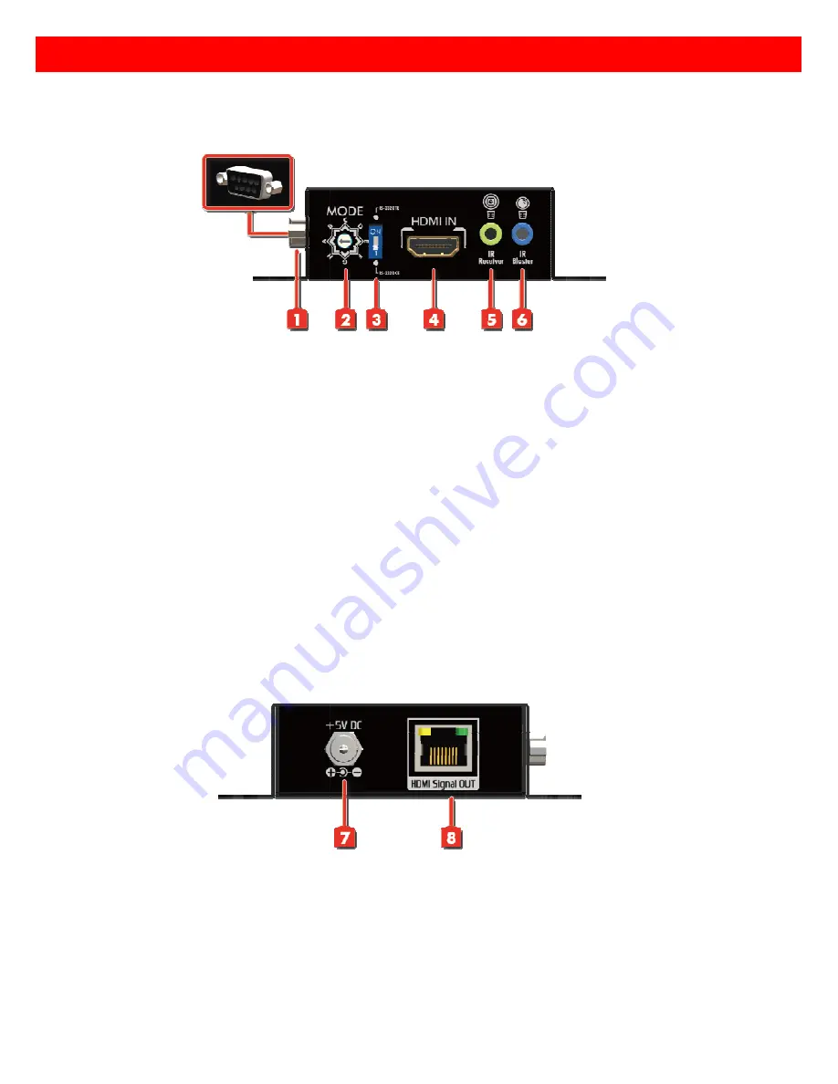
background image

PANEL

Transmitting unit

Front Panel 

1.

   RS-232: 

Connect to PC serial port with a DSUB

2.

  MODE:

  A - EDID Full-HD(1080p@60) 

B - EDID Full-HD(1080p@60) 

C - EDID Full-HD(1080p@60) 

D - EDID Full-HD(1080p@60) 

E - EDID HD(1080p@30)(1080i@60)(720p@60) 

F - EDID HD(1080p@30)(1080i@60)(720p@60) 

G - EDID Full-HD(1080p@60) 

H – Auto EDID learning   

3.

  Dip Switch: 

Setup the RS-232 mode for serial communication channel

4.

  HDMI IN:

 Connects to a HDMI source with a HDMI male

5.

  IR Receiver:

 Infrared 3.5mm socket for plugging in the extension cable of IR receiver

6.

  IR Blaster:

 Infrared 3.5mm socket for plugging in the extension cable of IR blaster


Rear Panel 


7.

  +5V DC:

 Connect to 5V DC power supply.

8.

   HDMI  Signal  OUT:

  Plug  in  a  Cat

HD-C5S4P-TX. 


PANEL DESCRIPTIONS

Transmitting unit


 HD-C5S4P-TX 


Connect to PC serial port with a DSUB-9 male-male cable here


1080p@60) - 24bit 2D video & 7.1ch audio   

HD(1080p@60) - 24bit 2D video & 2ch audio 

HD(1080p@60) - 24bit 3D video & 7.1ch audio 

HD(1080p@60) - 24bit 3D video & 2ch audio 

EDID HD(1080p@30)(1080i@60)(720p@60) - 24bit 2D video & 7.1ch audio

EDID HD(1080p@30)(1080i@60)(720p@60) - 24bit 2D video & 2ch audio

HD(1080p@60) - 36bit 2D video & 7.1ch audio 

232 mode for serial communication channel (see p.5 for details)

Connects to a HDMI source with a HDMI male-male cable


Infrared 3.5mm socket for plugging in the extension cable of IR receiver

Infrared 3.5mm socket for plugging in the extension cable of IR blaster


Connect to 5V DC power supply. 

Plug  in  a  Cat-5/5e/6  cable  that  needs  to  be  linked  to  the  transmitting  unit 

DESCRIPTIONS 

24bit 2D video & 7.1ch audio 

24bit 2D video & 2ch audio 

p.5 for details)


Infrared 3.5mm socket for plugging in the extension cable of IR receiver 

Infrared 3.5mm socket for plugging in the extension cable of IR blaster 

to  the  transmitting  unit 

Summary of Contents for HD-C5S4P

Page 1: ...over Single CAT with Bi directional IR RS Auto EDID Learning HDMI Extender over Single CAT X directional IR RS 232 Serial Auto EDID Learning User Manual HD C5S4P HDMI Extender over Single CAT X Serial and rev 120403 ...

Page 2: ...has been tested for conformance to safety regulations and requirements and has been certified for international use However like all electronic equipments the HD C5S4P should be used with care Please read and follow the safety instructions to protect yourself from possible injury and to minimize the Follow all instructions and warnings marked on this unit Do not attempt to service this unit yourse...

Page 3: ...ther insured This flexibility makes HDCP compliant DVD players or PS3 transmit utmost high quality video and audio with a greater distance at the minimal cost when integrating several components is also equipped with bi directional IR pass through path and RS bonus feature allows users to boost IR control distance up to 100m 330 ft and makes IR control possible through only single Cat 5 5e 6 cable...

Page 4: ...ex bi directional RS 232 support Yes Input 1x HDMI 1x 3 5mm 1x RJ45 1x 3 5mm Output 1x RJ45 1x 3 5mm 1x HDMI 1x 3 5mm In Out 1x DIN9 1x DIN9 HDMI source control Controllable via IR pass through from RX to TX and from TX to RX with IR extenders IR remote control Electro optical characteristics τ 25 Carrier frequency 20 60kHz HDMI connector Type A 19 pin female Min DIN connector DIN 9 RJ45 connector...

Page 5: ...rt with a DSUB 9 male male cable here 1080p 60 24bit 2D video 7 1ch audio HD 1080p 60 24bit 2D video 2ch audio HD 1080p 60 24bit 3D video 7 1ch audio HD 1080p 60 24bit 3D video 2ch audio EDID HD 1080p 30 1080i 60 720p 60 24bit 2D video 7 1ch audio EDID HD 1080p 30 1080i 60 720p 60 24bit 2D video 2ch audio HD 1080p 60 36bit 2D video 7 1ch audio 232 mode for serial communication channel see p 5 for ...

Page 6: ...The HDMI signal level varies from MAX strongest to MIN weakest for respective transmission length from longest possible range to short distance Please adjust the signal level from MIN to MAX and stop turning the rotary switch whenever the audio video is playing normally Inappropriate signal level setting may cause overpowering issue that would shorten the product life significantly 232 mode for se...

Page 7: ...ables Both TX and RX modules are set to DCE mode as default mode DIP switch down position This requires all RS232 9 Pin DB9 to be straight thru type To connect the TX module DB9 port to PC or control device a DB9 Male to Female cable is needed while connecting RX module DB9 female port to RS232 device a DB9 Male to Male cable is needed HD C5S4P RS232 port is only for controlling A V devices includ...

Page 8: ...PACKAGE CONTENTS 1x HD C5S4P TX RX 1x IR blaster 1x IR receiver 2x DC 5V 2A wall wart 1x User Manual CONNECTION DIAGRAM ...

Page 9: ...mmand signals received from the IR receiver from the other enf to control the devices corresponding to the IR signals plug in the IR receiver to receive all IR command signals from the IR remote controls of Definition of IR Earphone Jack IR Receiver extension cables in the market that are compatible to matrix if necessary for replacement use However work Incorrect placement of IR Blaster and Recei...

Page 10: ...of the receiving unit HD C5S4P RX 7 Plug in 5V DC power supply unit to the power jack of the transmitting unit HD C5S4P TX 8 If you see flickering or blinking image on the display please adjust the rotary control switch to improve the cable skew MAX stands for the strongest HDMI signal level for longest possible transmission length while MIN stands for the weakest HDMI signal level for short trans...

Page 11: ...eld Pin 12 TMDS Clock Pin 3 TMDS Data2 Pin 13 CEC Pin 4 TMDS Data1 Pin 14 Reserved N C on device Pin 5 TMDS Data1 Shield Pin 15 SCL Pin 6 TMDS Data1 Pin 16 SDA Pin 7 TMDS Data0 Pin 17 DDC CEC Ground Pin 8 TMDS Data0 Shield Pin 18 5V Power Pin 9 TMDS Data0 Pin 19 Hot Plug Detect Pin 10 TMDS Clock CAT5 RJ45 ...

Page 12: ...Generator VG 859C VG 870B The transmission length is largely affected by the type of Cat 5 5e 6 cables the type of HDMI sources and the type of HDMI display The testing result shows solid UTP cables usually in the form of 300m 1 000ft bulk cables can transmit a lot longer signals than stranded UTP cables usually in the form of fixed length patch cords Shielded STP cables are better suited than uns...

Page 13: ...gree to insure the unit or assume the risk of loss or damage in transit Under no circumstances will a unit be accepted without a return authorization number The warranty is in lieu of all other warranties expressed or implied including without limitations any other implied warranty or fitness or merchantability for any particular purpose all of which are expressly disclaimed Proof of sale may be r...

Reviews: