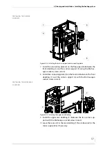
4 Planning and installation – Installing the heating system
42
4.
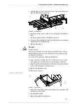
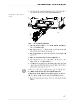
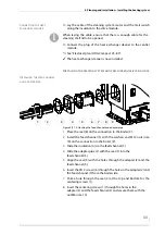
Transport the boiler to its installation site.
5.
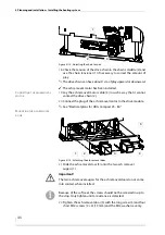
Place the boiler at the planned location while observing the min-
imum clearances.
✎
See “4.1 Dimensions”, section “Required room sizes and minimum
clearances” in this chapter.
6.
Align the boiler with plastic plates or flat steel strips (not included
in the scope of delivery) so that it is level.
✓
The boiler is erected.
I
NSTALLING
THE
COMBUSTION
FAN
1.
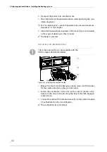
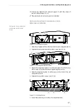
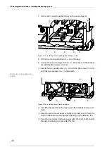
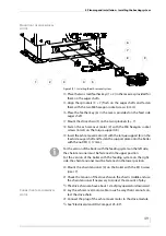
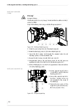
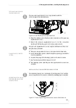
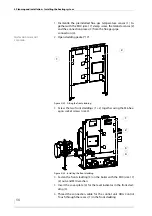
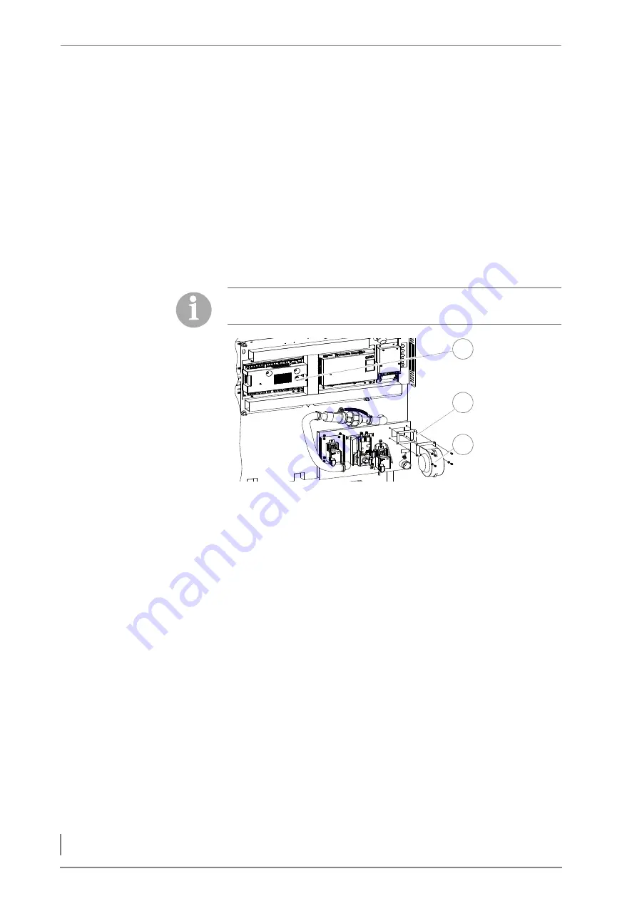
Release the four 5 mm M6 hexagon socket screws (3) of the intake
for the combustion fan on the air control unit.
2.
Fasten the combustion air fan (3) (with a seal (2) placed in be-
tween) to the air control unit using the four (5 mm) M6 hexagon
socket screws.
3.
Connect the cable of the combustion air fan to the central module
(1) as illustrated in the circuit diagram.
✓
The combustion fan is installed.
The combustion air fan is only available with the
HDG Compact 45/50/65/80 boiler.
Figure 4/8 - Installing the combustion fan
Zu
Auf
2
1
3


