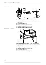
4 Planning and installation – Installing the heating system
62
33.
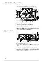
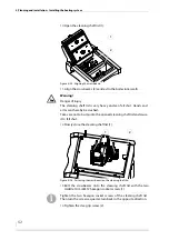
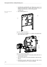
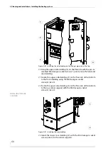
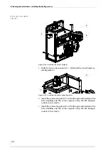
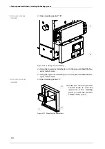
Hang the upper front panel on the feed side (1) using the pre-as-
sembled M6 hexagon socked screws.
I
NSTALLING
THE
TOP
COVERS
34.
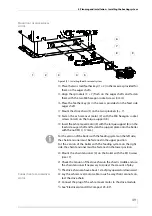
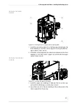
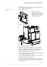
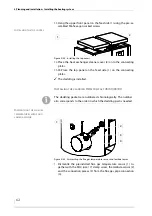
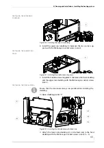
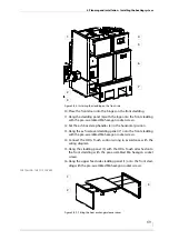
Place the heat exchanger cleaner cover (2) onto the connecting
plates.
35.
35.Place the top panel on the feed side (1) on the connecting
plates.
✓
The cladding is installed.
I
NSTALLING
THE
CLADDING
HDG C
OMPACT
45/50/65/80
D
ISMANTLING
THE
FLUE
GAS
TEMPERATURE
SENSOR
AND
LAMBDA
SENSOR
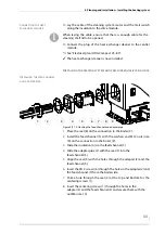
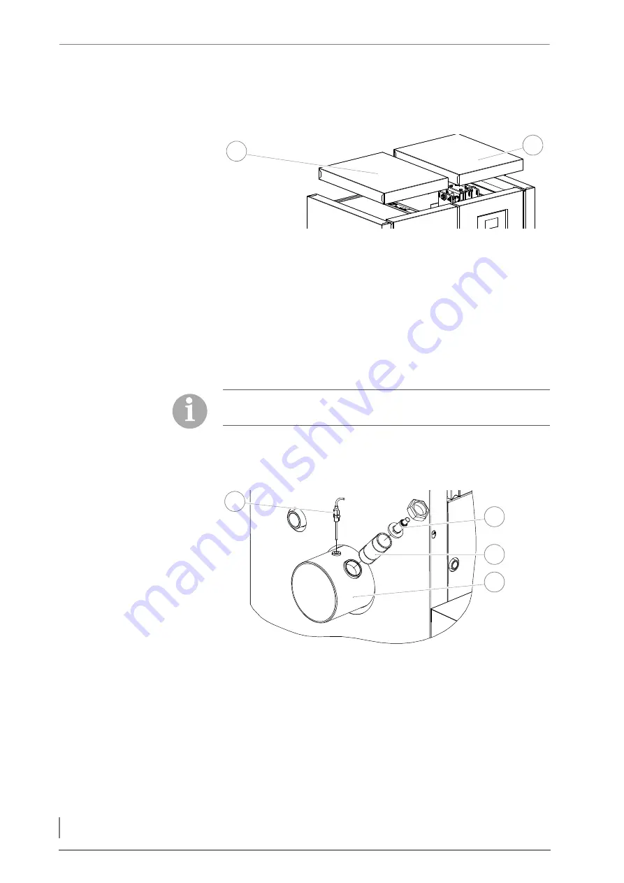
1.
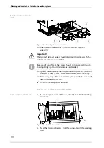
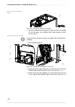
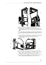
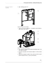
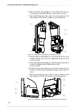
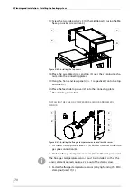
Dismantle the preinstalled flue gas temperature sensor (1) to-
gether with the M10 (size 17) clamp screw, the lambda sensor (2)
and the connection pieces (3) from the flue gas pipe connection
(4).
Figure 4/44 - Installing the top covers
1
2
The cladding packets are numbered chronologically. The number
also corresponds to the order in which the cladding part is needed.
Figure 4/45 - Dismantling the flue gas temperature sensor and lambda sensor
3
1
4
2

