background image

3 Mode of operation – Fuel quality requirements

29

the fuel classes 4 (wood chips), 5 (shavings), 5a (pellet) may be used
in the HDG Compact 25 - 80 heating system and also for  fuel classes
6 and 7 for the HDG Compact 45/50/65/80.

F

UEL


CLASS

 6

Painted, varnished or coated wood including remains thereof, pro-
vided no wood protection agents have been applied or are present
as the result of a treatment, and coatings do not contain organic hal-
ogen compounds or contain heavy metals.

F

UEL


CLASS

 7

Plywood, chipboard, fibreboard or otherwise glued wood including
remains thereof, provided no wood protection agents have been ap-
plied or are present as the result of a treatment, and coatings do not
contain organic halogen compounds or heavy metals.

Fuel classes 6 or 7 may only be used in a wood processing plant at 30
kW or more nominal thermal power. In the case of painted, varnished
or coated wood, it should be noted that greater stress can be placed
on the wearing parts such as combustion chamber, fill level and
lambda sensors, which may reduce their service lives.

N

OMINAL


THERMAL


VALUE


DEPENDING


ON


WATER


CONTENT

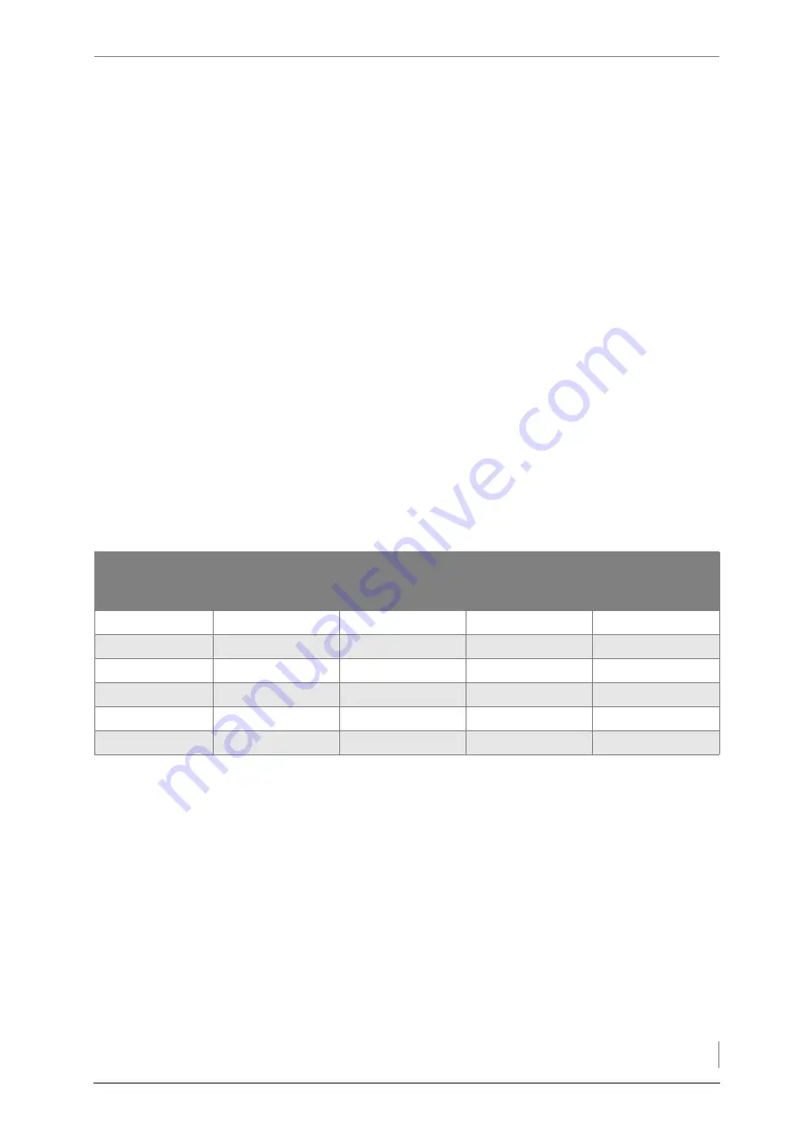
The following table indicates the maximum nominal thermal power
depending on water content, in reference to the fuels approved for
the HDG Compact 25 - 80 in accordance with DIN EN ISO 17225 “Bio-
genic solid fuel - fuel specifications and classes”.

A1 P31S, M20, A1.0 
wood chips and A1 

pellets

A1 P45S, M25, A1.0 

wood chips 

A1 D60, L50, M12, 

A1.0 pressed wood 

briquettes

A1 shavings

M20, A1.0 

HDG Compact 25

31 kW and 26 kW

28 kW

-

-

HDG Compact 35

31 kW and 35 kW

28 kW

-

-

HDG Compact 45

45 kW

43 kW, (42 kW)

43 kW

42 kW, (40 kW)

HDG Compact 50

50 kW

48 kW

48 kW

47 kW

HDG Compact 65

65 kW

63 kW 

63 kW

62 kW

HDG Compact 80

80 kW and 85 kW

78 kW

78 kW

77 kW

Table 3/5 - Max. nominal thermal power depending on water content

Summary of Contents for Compact 25

Page 1: ...hdg bavaria com HDG Compact 25 35 HDG Compact 45 50 65 HDG Compact 80 Operating manual ...

Page 2: ......

Page 3: ...0 front side 18 HDG Compact 45 50 65 80 back side 19 3 2 Functional description 20 Overview of heating system 20 Combustion process 21 Boiler and weather compensated heating control HDG Control 22 3 3 Technical data 23 HDG Compact 25 35 23 HDG Compact 45 50 65 80 24 3 4 Fuel quality requirements 25 Wood chips 25 Wood pellets 27 Pressed wood briquettes 28 Recommended fuel 28 Permitted fuel in accor...

Page 4: ...gas temperature sensor and lambda sensor 70 Attaching the pressure equalisation hose 71 Wiring the modules 72 Installing and adjusting the ash containers 72 Connecting the chimney 73 4 6 Delivery system 74 4 7 Electrical system 74 4 8 Water 74 4 9 Thermal safety device 75 5 Commissioning the system 77 5 1 Requirements 77 5 2 Procedure 78 6 Using the heating system 79 6 1 Control unit HDG Control 7...

Page 5: ...g and cleaning the lambda sensor 93 Cleaning the flue gas pipe 94 Cleaning the ash removal system 95 Cleaning the flue gas temperature sensor 96 Cleaning the ignition fan 96 Cleaning the flue gas fan 98 Cleaning the pressure equalisation hose 99 Cleaning and lubricating the overfill lever 99 Checking the fuel storage 101 8 Notes on dismantling and disposal 102 8 1 Dismantling 102 8 2 Disposal 103 ...

Page 6: ...Operation Manual HDG Compact 25 80 Content 6 ...

Page 7: ...tructions on standards regulations and work sheets should be checked before use and should be compared with the regulations applying locally at the site where the system is in stalled We reserve the right to make changes which may then differ from the technical details and illustrations in this Operating manual COPYRIGHT Written permission is required from HDG Bavaria GmbH for re printing storage ...

Page 8: ...stem and who is responsible for its maintenance 8 Notes on dismantling and disposal what has to be considered when dismantling and disposing of the heating system Table 1 1 Structure of the Operating manual Term Explanation Actuator This is a component which carries out a certain function in the heating system e g the stoker auger Ash removal augers These transport the combustion chamber ash and f...

Page 9: ... the combustion chamber from the silo and transport unit and acts as back burn protection Sensor Records certain parameters temperature fill level and forwards them to the control for analysis Stoker auger Carries the fuel from the rotary feeder into the combustion cham ber Wood chips B1 Machine chopped wood with a water content of between 15 to 35 percent in accordance with EN 303 5 Term Explanat...

Page 10: ...d on the safe use of the device and understand the resulting risks Children may not play with the device Cleaning and user main tenance must not be carried out by children without supervision BASIC PRINCIPLES FOR THE CONTENT OF THE OPERATING MANUAL SCOPE The content of this operating manual is intended exclusively for the planning installation and operation of the HDG Compact 25 80 heating systems...

Page 11: ...h the hot surfaces of the boiler can lead to burns Wait until the boiler has cooled down before touching non insu lated components Danger Danger of asphyxiation and explosion from carbon monoxide When the boiler is in operation carbon monoxide escaping from open cleaning or inspection hatches can cause asphyxiation or ex plosions Do not leave these open any longer than necessary Warning Danger of ...

Page 12: ...en working on the automatic ash removal or on the automatic heat exchanger cleaner hands and arms could be injured Turn off the main switch when performing any work on these com ponents Danger Dangerous electrical current or voltage The circuit boards and electrical components carry current Have work on electrical components performed only by a qualified electrician and turn the main switch off Wa...

Page 13: ...Danger of fire Working in areas marked with this symbol can lead to a fire Danger Danger of asphyxiation due to lack of oxygen When working in areas marked with this symbol there is a danger of asphyxiation due to high concentrations of carbon monoxide Danger Danger of explosion When working in areas marked with this symbol there is a danger of explosion due to high concentrations of carbon monoxi...

Page 14: ...system is required to read the Operating manual prior to beginning work particularly the chapter 2 Safety instructions This is especially important for persons who only occasionally work on the heating system for example when cleaning or servicing it The Operating manual must always be kept readily accessible at the place where heating system is installed Additional information for the operator ...

Page 15: ...t is also optionally available for the HDG Compact 25 65 When selecting the feeding unit for the HDG Compact 25 80 heating system you can choose between the following TBZ 150 for feeding wood chips shavings and pellets Pellet suction system with TBZ 90 for feeding pellets The HDG Compact 25 80 heating system can also be equipped with the following delivery systems FRA flexi blade delivery system H...

Page 16: ... fan 5 Flue gas pipe connection 6 Flue gas temperature sensor 7 Heat exchanger surfaces with cleaning turbulators in between 8 Ash removal augers 9 Tilting grate 10 Combustion chamber primary burning 11 Level indicator 12 Ignition pipe 13 Feeding system 14 Combustion chamber secondary burning Figure 3 1 Front side of the HDG Compact 25 35 boiler 12 6 4 3 2 14 13 5 1 10 7 11 9 8 ...

Page 17: ...le 4 Expansion module EM4 optional 5 Actuator primary air 6 Actuator secondary air 7 Ash removal motor 8 Grate tilting motor 9 Boiler return connection DN 32 IG 10 Filling draining connection DN 15 IG 11 Ignition fan 12 Central module 13 Lambda sensor 14 STL release button 15 Boiler supply connection DN 32 IG 16 Main switch Figure 3 2 HDG Compact 25 35 boiler back side 8 7 5 4 3 2 1 9 11 12 13 16 ...

Page 18: ... Flue gas pipe connection 7 Heat exchanger surfaces with cleaning turbulators in between 8 Ash walking floor delivery system 9 Ash removal augers 10 Combustion chamber primary burning 11 Tilting grate 12 Level indicator 13 Pressure equalisation hose 14 Feeding system 15 Ignition pipe 16 Combustion chamber secondary burning Figure 3 3 Front side of the HDG Compact 45 50 65 80 boiler 2 7 6 5 3 12 15...

Page 19: ... Central module 5 Drive module 6 Expansion module EM4 optional 7 Combustion air fan 8 Actuator primary air 9 Ash removal motor 10 Grate tilting motor 11 Ignition fan 12 Actuator secondary air 13 Boiler return connection DN 32 IG and DN 40 IG 14 STL release button 15 Main switch 16 Filling draining connection DN 15 IG Figure 3 4 HDG Compact 45 50 65 80 boiler back side 1 8 7 4 2 5 16 3 6 15 13 10 1...

Page 20: ...tion 20 3 2 Functional description OVERVIEW OF HEATING SYSTEM The HDG Compact 25 80 heating system may contain the following components 1 Delivery system 2 Feeding system 3 HDG Compact 25 80 boiler with HDG Control Figure 3 5 Overview 1 2 3 ...

Page 21: ...dary air is provided based on the combustion requirements The ash produced during combustion is removed by tipping the grate 7 at regular intervals The automatic cleaning 4 removes the lighter fly ash from the heat exchanger surfaces 3 periodically by raising and lowering the turbulators The ash falls into either an ash pan in the base of the boiler or onto ash removal augers 6 which extract the w...

Page 22: ...up information on the current process The fuel feeding delivery dosing and feeding is also controlled by the HDG Control HEATING CIRCUIT CONTROL The HDG Control controls the entire energy management of the heating system including the following depending on the version Accumulator management Weather compensated heating circuits Domestic hot water heating Peak load boiler control District heating p...

Page 23: ...ning data for flue calculation DIN EN 13384 1 Flue gas temperature Tw at Nominal thermal power minimum thermal power 160 C 110 C Flue gas mass flow at Nominal thermal power minimum thermal power 0 0210 0 0170 kg s 0 0070 kg s 0 0210 0 0230 kg s 0 0070 kg s CO2content at Nominal thermal power minimum thermal power 12 1 12 2 11 3 8 9 12 1 12 5 11 3 8 9 Flue draught requirement Pw 7 Pa Diameter of fl...

Page 24: ...0 kg Planning data for flue calculation DIN EN 13384 1 Flue gas temperature Tw at Nominal thermal power minimum thermal power 160 C 105 C 180 C 110 C 160 150 C 105 C Flue gas mass flow at Nominal thermal power minimum thermal power 0 029 0 026 kg s 0 0125 kg s 0 0326 kg s 0 0125 kg s 0 0414 0 0375kg s 0 0182 0 0144kg s 0 0520 0 0440kg s 0 0250 0 0170kg s CO2 content at Nominal thermal power minimu...

Page 25: ...n Air inlet cross section 150 cm 180 cm 210 cm Boiler type HDG Compact 45 Wood chips pellets HDG Compact 50 Wood chips pellets HDG Compact 65 Wood chips pellets HDG Compact 80 Wood chips pellets Table 3 2 Technical data With regard to the quality standards for solid fuel DIN EN ISO 17225 Biogenic solid fuel fuel specifications and classes classification of wood chips applies Part 4 Classification ...

Page 26: ...and 25 M25 for the HDG Com pact 45 50 65 80 and complies with the property class A1 The water content of the wood chips may not be under 10 M10 as a higher aerosol formation causes a higher level of dust For technical considerations a representative calorific value is se lected depending on water content For burning that is both eco nomical and low on emissions the calorific value should not be le...

Page 27: ...ery system HDG hinged arm delivery system or HDG pellet delivery system PSZ the diameter can also comply with D08 D06 The diameter of the pellets must be 6 mm 1 mm The length of the pellets must measure between 3 15 mm and 40 mm A maximum of 1 0 by weight of the pellets may be longer than 45 mm D08 The diameter of the pellets must be 8 mm 1 mm The length of the pellets must measure between 3 15 mm...

Page 28: ...measures filter technology may be necessary for complying with the dust emission values according to the 1st Federal Emission Control Ordinance 2nd stage RECOMMENDED FUEL It is important that fuel is used according to HGD fuel specifications in order to be able to guarantee compliance with emission limit values under the 1st Federal Emission Control Ordinance 2nd stage In particular all fuel requi...

Page 29: ...t at 30 kW or more nominal thermal power In the case of painted varnished or coated wood it should be noted that greater stress can be placed on the wearing parts such as combustion chamber fill level and lambda sensors which may reduce their service lives NOMINAL THERMAL VALUE DEPENDING ON WATER CONTENT The following table indicates the maximum nominal thermal power depending on water content in ...

Page 30: ...ler height A 1655 1920 1920 Flow connection height B 1175 DN32 IG 1400 DN32 IG DN40 IG Height at middle of the flue gas pipe connection C 820 1280 1280 Return connection height D 340 DN32 IG 340 DN32 IG 340 DN40IG Depth of boiler without attachments and ash removal E 700 830 830 Depth of boiler with attachments and ash removal F 1100 1300 1300 Diameter of flue pipe connection 150 180 200 Table 4 1...

Page 31: ...t of input for safety heat exchanger A 1155 DN15 AG 1380 DN15 AG 1380 DN15 AG Height of output for safety heat exchanger B 1155 DN15 AG 1340 DN15 AG 1340 DN15 AG Width of boiler without attachments and flue gas pipe connection C 1150 1150 1450 Width of boiler with attachments and flue gas pipe connection D 2200 2110 2420 Table 4 2 Dimensions on back side HDG Compact 25 80 mm ...

Page 32: ...ominal thermal power of more than 50 kW may only be installed in special boiler rooms APPLICABLE REGULATIONS Local building regulations always apply In Germany individual state regulations on boilers and furnaces FeuVO also apply Figure 4 3 Required room sizes and minimum clearances C F B D A E A B C D E F Minimum room height Recom mended room height HDG Compact 25 35 2900 700 1800 400 700 1200 19...

Page 33: ... accessible for the filling process free of other installations especially in existing buildings adapted to fuel requirements The refilling intervals should be kept as long as possible The HDG Compact 25 80 heating system should be located so that the noise generated does not exceed the permitted values of DIN 4109 Soundproofing in building construction PROPER DIMENSIONING The size of the fuel sto...

Page 34: ...ed which meets the re quirements of DIN EN 13384 1 2003 03 Thermal and fluid dynamic calculation methods If it does not meet this standard contact your specialist heating company or chimney engineer Another essential criterion is meeting the flue draught requirement This depends on three major factors CHIMNEY CHARACTERISTICS The requirements for minimising the draught loss in the chimney are Good ...

Page 35: ...trance into it to the end of the chimney CONNECTING THE BOILER TO THE CHIMNEY The firing system must be connected with a connecting piece which is as short as possible at an angle which is less than 30 45 to the chimney You should aim for a connecting piece with a maximum length of 1 m using just one fitting Every additional fitting results in a greater pressure loss in the exhaust path and should...

Page 36: ...ectives of 2006 95 EC low voltage guidelines must be fol lowed for the electrical connections to the system No electrical installations such as power sockets distribution boxes lights or light switches may be located in the fuel storage Any lights must be suitable for use in areas at risk of explosion The VDE regula tions for rooms with a risk of dust explosion must be followed The required connec...

Page 37: ...the proportion of external energy supplied and to lower wear of the mechanical com ponents One further advantage of the accumulator is in summer operation when only hot water is required When operating in this mode the accumulator helps avoid frequent ON OFF switching For the above mentioned reasons we recommend an accumu lator even for automatic boiler systems SAFETY DEVICES Safety devices e g bo...

Page 38: ...livery HDG Compact 25 80 boiler Cladding x included o optional Feeding system customer specific Delivery system customer specific Cleaning tools Operating documentation Upon delivery check that the scope of delivery matches the informa tion on the delivery note The pipe dimensions must be adapted to meet the requirements at the site Take the water side connections of the boiler for the supply and ...

Page 39: ...alists to perform the installation Danger Dangerous electrical current or voltage Working on live components can result in an electric shock Switch off the mains supply to the heating system during the instal lation Important When laying the pipelines observe the minimum required clear ances See section 4 1 Dimensions in this chapter Important Due to the noise we recommend acoustic insulation meas...

Page 40: ... The boiler weighs over 600 kg If the boiler is dropped during trans port persons can be seriously injured and the boiler can be dam aged Make sure that you use appropriate lifting gear when placing the boiler The boiler packaging can be taken to the local recycling company Important When using the installation aid observe the required minimum clearance of 60 cm to the side walls in order to be ab...

Page 41: ...boiler rests completely on the floor 11 Align the boiler with plastic plates or flat steel strips not included in the scope of delivery so that it is level 12 Remove the installation aid The boiler is erected TRANSPORT WITH A CRANE 1 Fasten the crane hooks on the crane eyelets 3 according to the instructions on the sticker 2 Carefully lift the boiler 3 Remove the pallet from the boiler Figure 4 6 ...

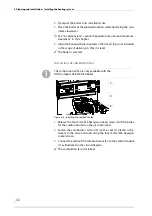
Page 42: ...it is level The boiler is erected INSTALLING THE COMBUSTION FAN 1 Release the four 5 mm M6 hexagon socket screws 3 of the intake for the combustion fan on the air control unit 2 Fasten the combustion air fan 3 with a seal 2 placed in be tween to the air control unit using the four 5 mm M6 hexagon socket screws 3 Connect the cable of the combustion air fan to the central module 1 as illustrated in ...

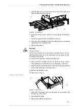
Page 43: ...h the M10 size 17 nut and M10 spring ring to the welded screw 3 Hang each ash door 3 with the semi circular rivets into the hinges 4 Assemble the door cladding 1 with the M5 size 8 screws and M5 washer onto the ash door 3 5 Place the ash pan 4 in the ash compartment 6 Seal each ash door 3 using the star grip screw 2 The manual ash removal is installed Figure 4 9 Installing the sealing plates 1 3 2...

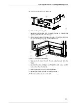
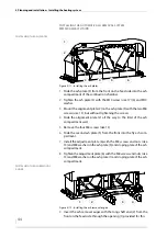
Page 44: ...it of the ash compartment wall 5 Remove the four M8 screws size 13 6 Slide the second ash plate 5 from the front into the fly ash com partment 7 Install the adjustment plate 6 with the M8 screws and nuts size 13 and M8 washer on the ash plate 5 and sloping plate of the ash compartment 8 Tighten the adjustment plate 6 with the M8 screws and nuts size 13 and M8 washer on the ash plate 1 and sloping ...

Page 45: ...drive chain 9 on the two sprockets 1 6 15 Fasten the ash removal motor 8 with the M8 hexagon socket screws 6 mm on the torque support 7 16 Insert the ash removal motor 7 with the torque support 6 on the feed side auger shaft and fasten the support plate onto the boiler with the M10 screw and nut size 17 17 Mount the chain tensioner 3 on the boiler with the M10 screw size 17 Figure 4 13 Mounting th...

Page 46: ...ect the plug of the ash removal motor to the drive module See Electrical plans for HDG Compact 25 80 MOUNTING THE ASH REMOVAL DOOR 21 Slide the ash removal door 5 onto the two ash removal augers 1 22 Tighten the ash removal door 5 with the long screw 3 and four short M12 screws 2 4 19 mm and the M12 washers evenly Figure 4 14 Adjusting the chain tension 1 2 3 Figure 4 15 Attaching the ash removal ...

Page 47: ...e ash plate 2 from the front into the ash compartment 1 2 Tighten the ash plate 2 with the M10 screw size 17 3 3 Mount the alignment plate 1 on the ash plate 3 with the two M10 screws 2 without however tightening the screws 4 Slide the alignment plate 1 all the way to the limit of the ash compartment wall 5 Tighten the two M10 screws size 17 2 6 Insert the centre tray 2 in the ash compartment 4 Fi...

Page 48: ...s 13 mm with the spacer plates 6 7 underneath INSTALLING THE ASH REMOVAL AUGER 11 Install the bracket 5 on the moving ash floor with M10 screws 17 mm 12 Insert the ash removal auger with the long shaft end 3 from the front on the feed side through the opening 1 provided for this 13 Insert the second ash removal auger with the short shaft end 4 through the opening 2 provided for this Figure 4 19 In...

Page 49: ...he boiler with the nut M10 17 mm 20 Mount the chain tensioner 4 on the boiler with the M10 screw size 17 21 Check the tension of the drive chain in the chain s middle and use the chain tensioner if necessary to correct the amount of play The drive chain can have about 1 cm of play upward or downward CONNECTING THE ASH REMOVAL MOTOR 22 Lay the ash removal motor cable in such a way that it cannot co...

Page 50: ... The ash removal system is installed INSTALLING THE HEAT EXCHANGER CLEANER INSTALLING THE CROSSBEAMS 1 Release the pre mounted M12 nuts size 19 from the short or long crossbeam 2 Place the two crossbeams 1 on the turbulators in the cleaning shaft Figure 4 22 Mounting the ash removal door 5 1 4 2 3 Important The two ash removal augers must not come into contact with the ash removal door when instal...

Page 51: ...on the hinges 2 of the cleaning shaft lid on the boiler 6 Fold up the hinges 2 7 Place the cleaning shaft lid 1 on the boiler 8 Guide the screws 2 of the hinges into the holes on the cleaning shaft lid 1 9 Bolt on the cleaning shaft lid 1 with the M12 nuts on the hinges using a 19 mm spanner Warning Danger of injury The cleaning shaft lid is very heavy Hands can become crushed when installing it A...

Page 52: ...ocket screws 1 14 Tighten the star grip screw 2 Figure 4 25 Aligning the crossbeams 1 2 Warning Danger of injury The cleaning shaft lid is very heavy and can fall shut Hands and arms can thereby be crushed Take care not to bump into the opened cleaning shaft lid and cause it to fall shut Figure 4 26 Fastening the crossbeams on the cleaning shaft lid 1 2 Tighten the two hexagon socket screws of the...

Page 53: ...with the washers and M12 nuts size 19 on the connection to the boiler 9 3 Slide the insulation 4 via the feed channel 5 4 Slide the adapter pipe 2 with the seal 3 into the feed channel 5 5 Align the seal 3 with the holes through the adapter 2 and the feed channel 5 6 Insert the M12 screws 6 through the holes in the adapter 2 and the feed channel 5 from the boiler side 7 Poke a hole through the sea...

Page 54: ...ng system 1 14 Fit the DN40 plug 3 in to the front equalisation tube connection 2 on the feeding system INSTALLING THE SUPPORT LEG Warning Danger of injury The feeding system is very heavy Hands and feet could be crushed when it is lifted Only lift the feed system using suitable lifting equipment Figure 4 28 Attaching the feeding system 5 4 3 2 1 6 15 Fit the support leg 4 with a 19 mm M12 screw 3...

Page 55: ... of the feeding system to the drive module See Electrical plans HDG Compact 25 80 The feeding system and the pressure equalisation hose are now installed INSTALLING THE CLADDING HDG COMPACT 25 35 DISMANTLING THE FLUE GAS TEMPERATURE SENSOR AND LAMBDA SENSOR The pressure equalisation hose is only available with the HDG Compact 45 50 65 80 boiler Figure 4 30 Attaching the pressure equalisation hose ...

Page 56: ...Open cladding packet 1A 3 Screw the two front claddings 1 2 together using the M6 hex agon socket screws size 4 4 Fasten the front cladding 3 on the boiler with the M10 size 17 2 nuts and M10 washers 5 Insert the cover plate 4 for the level indicator in the front clad ding 3 6 Thread the connection cable for the control unit HDG Control Touch through the recess 1 in the front cladding Figure 4 32 ...

Page 57: ... the feed side between the front cladding 1 and the corner support 4 with the M6 hexagon sockets screws size 4 INSTALLING THE UPPER REAR CLADDING 9 Install the upper rear cladding 1 between the two corner sup ports with the M6 hexagon socket screws size 4 10 Leave the recess 2 in the rear cladding 1 free to be wired to the mains supply later if necessary Figure 4 34 Installing the corner supports ...

Page 58: ... Open cladding packet 2 13 Attach the lower side cladding 2 on the feed side to the front cladding with the M6 hexagon socket screws size 4 1 3 14 Attach the lower side cladding 2 on the feed side to the rear corner support with the M6 hexagon socket screws size 4 4 5 Figure 4 36 Installing the middle connecting plate 1 Ensure that the clearances always run parallel when installing the cladding Fi...

Page 59: ...e the upper side cladding 2 on the feed side at the bottom to the rear corner support using the M6 Hexagon socket screws 4 size 4 18 Fasten the lower side cladding 4 on the flue side to the front cladding with the M6 Hexagon socket screws 3 5 size 4 19 Secure the lower side cladding 4 on the flue side to the rear corner support using the M6 Hexagon socket screws 1 2 Figure 4 38 Installing the side...

Page 60: ...ttom to the front cladding using the M6 Hexagon socket screw 4 size 4 22 Fasten the upper side cladding 3 on the flue side at the bottom to the rear corner support with the M6 Hexagon socket screw 2 size 4 INSTALLING THE REAR CLADDING 23 Install the lower rear cladding 2 with the M6 hexagon socket screws size 4 to the corner supports Figure 4 40 Installing the side cladding on the flue gas pipe si...

Page 61: ...sh box levers to horizontal 30 Hang the lower front panel 7 onto the front cladding using the pre assembled M6 hexagon socked screws 31 Connect the HDG Touch wiring according to the circuit diagram See Electrical plans HDG Compact 25 80 32 Hang the upper front panel 5 with the HDG Touch control at tached onto the front cladding using the pre assembled M6 hex agon socked screws 26 Install the contr...

Page 62: ...led INSTALLING THE CLADDING HDG COMPACT 45 50 65 80 DISMANTLING THE FLUE GAS TEMPERATURE SENSOR AND LAMBDA SENSOR 1 Dismantle the preinstalled flue gas temperature sensor 1 to gether with the M10 size 17 clamp screw the lambda sensor 2 and the connection pieces 3 from the flue gas pipe connection 4 Figure 4 44 Installing the top covers 1 2 The cladding packets are numbered chronologically The numb...

Page 63: ...cket screws size 4 2 Fasten the front cladding 3 to the boiler with the M10 size 17 2 nuts and M10 washers 3 Insert the cover plate 4 for the level indicator in the front clad ding 3 4 Thread the connection cable for the control unit HDG Control Touch through the recess 1 in the front cladding Figure 4 46 Fitting the front cladding 2 1 Figure 4 47 Installing the front cladding 4 3 1 2 ...

Page 64: ... connecting plate 1 on the flue pipe side between the front cladding and the corner support using the M6 hexagon sockets screws size 4 7 Install the connecting plate 2 on the flue pipe side between the front cladding and the corner support using the M6 hexagon sockets screws size 4 Figure 4 48 Installing the corner supports 2 1 3 Figure 4 49 Installing the outer connecting plate 2 1 ...

Page 65: ...ladding and the upper rear cladding with the M6 hexagon sockets screws size 4 INSTALLING THE SIDE CLADDING 10 Open cladding packet 2 11 Attach the lower side cladding 2 on the feed side to the front cladding with the M6 hexagon socked screws size 4 1 3 Figure 4 50 Installing the upper rear cladding 1 Figure 4 51 Installing the middle connecting plate 1 Ensure that the clearances always run paralle...

Page 66: ...mbled M6 hexagon socket screws 1 size 4 15 1Fasten the upper side cladding 2 on the feed side at the bottom to the front cladding with the M6 Hexagon socket screws 3 size 4 16 Secure the upper side cladding 2 on the feed side at the bottom to the rear corner support using the M6 Hexagon socket screws 4 size 4 17 Screw the M6 hexagon socket screw 5 size 4 loosely into the side cladding so that the ...

Page 67: ... flue side upper side cladding 5 onto the front cladding and rear cladding using the pre assembled M6 Hexagon socket screws 1 size 4 22 Secure the upper side cladding 5 on the flue side at the bottom to the front cladding with the M6 Hexagon socket screw 6 size 4 23 Fasten the upper side cladding 5 on the flue side at the bottom to the rear corner support with the M6 Hexagon socket screw 4 size 4 ...

Page 68: ...ex agon socket screws 27 Hang the upper rear cladding 1 on to the preassembled M6 hex agon socket screws INSTALLING THE FRONT CLADDING 28 Open cladding packet 4 Figure 4 56 Installing the rear cladding 2 1 29 Install the control unit HDG Control Touch 1 with the spacers 2 in the cladding panel 3 with the washers and M4 screws size 7 Figure 4 57 Mounting the control unit 1 1 3 2 ...

Page 69: ...o the front cladding with the pre assembled M6 hexagon socket screws 34 Connect the HDG Touch control wiring in accordance with the wiring diagram 35 Hang the cladding panel 5 with the HDG Touch attached onto the front cladding with the pre assembled M6 hexagon socket screws 36 Hang the upper feed side cladding panel 1 onto the front clad ding with the pre assembled M6 hexagon socket screws INSTAL...

Page 70: ...g plates The cladding is installed INSTALLING THE FLUE GAS TEMPERATURE SENSOR AND LAMBDA SENSOR 1 Fit the M10 clamp screw size 17 2 and M10 washer in the flue gas pipe connection 6 2 Slide the flue gas temperature sensor 1 into the clamp screw 2 3 Fasten the flue gas temperature sensor 2 by tightening the M10 clamp nut size 17 1 Figure 4 60 Installing the top covers 1 2 3 4 Figure 4 61 Installing ...

Page 71: ...e lambda sensor are now installed ATTACHING THE PRESSURE EQUALISATION HOSE 7 Place the rubber seal on the boiler end connection of the pressure equalisation hose 2 8 Attach the pressure equalisation hose 2 to the connection bushing of the boiler 1 using a pipe wrench 9 Set the position indicator 1 for the pressure equalisation regu lator to approximately half open The pressure equalisation hose is...

Page 72: ...Remove the ash containers from the packaging 2 Lift up the clamp handle 1 Depending on the hydraulic application an EM 4 expansion module may have to be used Important If the EM4 expansion module is used this must be installed on the rear next to the drive module If expansion module EM8 or EM8 4 is used instead or in addition it must be installed external boiler For connecting the expansion module...

Page 73: ...ers in the reverse sequence 12 If required adjust the height of the wheels 2 so that they are flush with the floor The ash containers are mounted and adjusted CONNECTING THE CHIMNEY See section 4 3 Connections in this chapter 1 Connect the flue gas pipe to the chimney connection 2 Make sure that the connecting piece does not protrude into the chimney 3 Seal the connection to the chimney with highl...

Page 74: ... built in dia phragm for integration in water installations Before putting the system into operation the pressure of the dia phragm expansion vessel must be adjusted for the conditions in the heating system and in the building After putting the system into operation heat up the system to the maximum boiler temperature and bleed air from the system again to make sure that there are no air pockets T...

Page 75: ...nger and thermal safety device can only serve their purpose if the following requirements have been met A flow pressure of at least two bar and a flow rate of 1800 l h must be available at the cold water inlet of the safety heat exchanger The distance between the supply and return lines of the thermal safety device and the safety heat exchanger should not be less than their nominal width The suppl...

Page 76: ... Safety heat exchanger inlet DN 15 male HDG COMPACT 45 50 65 80 1 Connection of immersion sensor for thermal safety device DN 15 inside thread 2 Safety heat exchanger inlet DN 15 outside thread 3 Safety heat exchanger outlet DN 15 male 4 Thermal safety device TAS 5 Tundish connection to drainage system Figure 4 67 Installing the thermal safety device HDG Compact 25 35 1 2 3 4 5 Figure 4 68 Install...

Page 77: ...The heating system has been filled with water as specified The heating system has been bled The pressure of the membrane expansion vessel has been adapted to on site conditions All required DIN EN 12828 safety devices have been installed and are ready for operation The power supply to all components is ensured Makeshift solu tions are not sufficient All doors and openings on the boiler and on the ...

Page 78: ...nual HDG Control Chapter 4 Commis sioning the system Danger Dangerous electrical current or voltage Isolate the mains cable to the heating system Important Commission the HDG Compact 25 80 heating system in accord ance with the specifications from the supplied commissioning pro tocol Caution Damage from smoke If the ash necks are empty or the ash containers are not at least half filled when commis...

Page 79: ...OR FILLING WITH WOOD CHIPS 1 Switch the heating system on See the HDG Control operating manual chapter 5 Using the control unit section 5 2 Switching on the heating system 2 Manually run the delivery system for 30 seconds or until the arms are folded into the dome at the start of the filling process 3 Fill the fuel storage room The filling of the fuel storage is completed Warning Damage to deliver...

Page 80: ...hapter 5 Using the control unit section 5 2 Switching on the heating system The filling of the pellet storage is completed 6 3 Performing a chimney sweep measurement See the HDG Control operating manual chapter 5 Using the control unit section 5 8 Performing a chimney sweep measure ment 6 4 Switching off the heating system for repair work 1 Switch the heating system off See the HDG Control operati...

Page 81: ...vals are guidelines Depending on the quality of the fuel and the power used by the heating system more frequent on off operation the intervals may vary Interval Component See page Weekly as required Cleaning the tilting grate Checking and empty the ash container Lubricate the feeding system 150 operating hours Lubricate the heat exchanger cleaner 40 oper ating hours 83 84 87 87 Every 6 months appr...

Page 82: ...Even when turned off they only cool down slowly Switch the heating system off and only start with the cleaning and maintenance work when the surfaces have cooled down Warning Risk of injury from automatically driven components If the heating system is switched on automatically driven compo nents can unexpectedly start running Limbs or fingers could be come caught and crushed Switch the heating sys...

Page 83: ...urn out and cool down 3 Turn the main switch off 1 Combustion chamber tem perature sensor 2 Secondary combustion chamber Figure 7 1 HDG Compact 25 35 combustion chamber temperature sensor 1 2 1 Combustion chamber tem perature sensor 2 Secondary combustion chamber Figure 7 2 HDG Compact 45 50 65 80 combustion chamber temperature sensor 1 2 1 Wall holder 2 Scraper 3 Cleaning brush Figure 7 3 Cleanin...

Page 84: ...aph Test 8 After cleaning close the combustion chamber door 2 and the front door 1 of the boiler 9 Re starting the heating system See the HDG Control operating manual chapter 5 Using the control unit section 5 2 Switching on the heating system The tilting grate is cleaned CHECKING AND EMPTYING THE ASH CONTAINER Figure 7 4 Cleaning the tilting grate 3 2 1 Important Observe the Generally applicable ...

Page 85: ... the heating system See the HDG Control operating manual chapter 5 Using the control unit section 5 2 Switching on the heating system The ash pans have been checked and emptied CHECKING AND EMPTYING ASH CONTAINERS AUTOMATIC ASH REMOVAL 1 Switch the heating system off See the HDG Control operating manual chapter 5 Using the control unit section 5 3 Switching off the heating system 2 Allow the fire ...

Page 86: ...reclose them 13 Mount the lid 4 on the ash container 3 and install the ash con tainer 3 in the boiler in the reverse sequence 14 Repeat the process for the second ash container See the HDG Control operating manual chapter 5 Using the control unit section 5 2 Switching on the heating system Inspection and emptying of the ash containers has been com pleted Figure 7 6 Checking and empty the ash conta...

Page 87: ...the fire in the heating system to burn out and cool down 3 Turn the main switch off 4 Remove the top cover 1 or the front 5 and the rear 3 covers of the heat exchanger cleaner Important Observe the Generally applicable safety instructions in this sec tion 1 Place the grease gun on the lubricating nipple 1 2 Press three strokes of grease into the feeding system The feeding system is lubri cated Fig...

Page 88: ...ol operating manual chapter 5 Using the control unit section 5 3 Switching off the heating system 2 Allow the fire in the heating system to burn out and cool down 3 Turn the main switch off 4 Remove the lower rear cladding 3 or 6 from the boiler Important Observe the Generally applicable safety instructions in this sec tion Warning Risk of injury from automatically driven components When the heati...

Page 89: ... Using the control unit section 5 2 Switching on the heating system The check of the drive chain of the ash removal system is com pleted CHECKING THE DRIVE CHAIN OF THE FEEDING SYSTEM 1 Switch the heating system off See the HDG Control operating manual chapter 5 Using the control unit section 5 3 Switching off the heating system 2 Allow the fire in the heating system to burn out and cool down 3 Tu...

Page 90: ... chain tensioner 3 The chain tensioner can be moved 7 Move the chain tensioner 3 to the side until the drive chain has sufficient tension again 8 Secure the chain tensioner 3 in this position The drive chain is tightened 9 Mount the chain guard 2 back on the feeding system 10 Re starting the heating system See the HDG Control operating manual chapter 5 Using the control unit section 5 2 Switching ...

Page 91: ...emove the cover 4 of the heat exchanger cleaner 6 In manual mode move the turbulators to the lowest position See the HDG Control operating manual chapter 6 Parameter HDG Compact 25 80 section 6 2 Boiler paragraph Test 7 Turn the main switch off Important Observe the Generally applicable safety instructions in this sec tion Warning Danger of injury The cleaning shaft lid is very heavy and can fall ...

Page 92: ...ery 14 Clean the crossbar shafts 1 and spray them with heat resistant grease 15 Reassemble the heat exchanger cleaner and the cleaning shaft lid in the reverse sequence 16 Replace the covers 17 Re starting the heating system Figure 7 12 Folding out the cleaning shaft lid 1 3 2 Figure 7 13 Pulling out the turbulators 1 2 For easier assembly align the push rods of the turbulators with the centre of ...

Page 93: ...bda sensor 2 for a secure fit 10 Carefully tighten the lambda sensor 2 in the ceramic seal with a 22 mm spanner 11 Re starting the heating system See the HDG Control operating manual chapter 5 Using the control unit section 5 2 Switching on the heating system The lambda sensor has been checked and cleaned Important Observe the Generally applicable safety instructions in this sec tion 4 Using a pip...

Page 94: ...n the heating system The cleaning of the flue gas pipe is completed Important Observe the Generally applicable safety instructions in this sec tion Caution Danger of burns from hot surfaces The surface of the flue pipe becomes very hot during operation Even when turned off it only cools down slowly Switch the heating system off and only start with the cleaning and maintenance work when the surface...

Page 95: ... 4 7 Undo the five fastening screws SW19 2 8 Pull the ash removal door 6 forward off the ash removal augers 9 Check the combustion chamber ash compartment 1 and the heat exchanger ash compartment 7 for foreign bodies encrusta tions or clumps of ash and remove these if necessary using a cleaning tools e g a scraper as included in delivery 10 Mount the components in the reverse sequence 11 Re starti...

Page 96: ...E IGNITION FAN Important Observe the Generally applicable safety instructions in this sec tion 4 Loosen the M10 clamp nut size 17 2 and pull the flue gas temperature sensor 1 out of the sensor clamp as sembly 2 5 Clean the sensor surface with a moist cloth Figure 7 17 Cleaning the flue gas temperature sensor 1 2 The flue gas temperature sensor must be installed so that the sensor projects approx 2...

Page 97: ...M4 stainless steel slotted screws 4 of the hot air nozzle 5 7 Pull off the hot air nozzle 5 8 Remove the insulating tube 6 and the seal 3 9 Pull the heating element 2 out of the plug contacts 7 10 Check the heating element 2 for dirt 11 Remove any dirt by blowing it off 12 Check the photocell 1 for dirt 13 Remove any dirt using a cotton swab 14 Reinstall the ignition fan into the heating system in...

Page 98: ...arting the heating system See the HDG Control operating manual chapter 5 Using the control unit section 5 2 Switching on the heating system The flue gas fan has been cleaned The flue gas fan is only available with the HDG Compact 25 35 boiler Important Observe the Generally applicable safety instructions in this sec tion Warning Risk of injury from automatically driven components When working on t...

Page 99: ...on hose 3 for dirt and dislodge it if necessary by forceful shaking and careful bending 7 Mount the pressure equalisation hose in the reverse sequence 8 Re starting the heating system See the HDG Control operating manual chapter 5 Using the control unit section 5 2 Switching on the heating system The pressure equalisation hose is cleaned CLEANING AND LUBRICATING THE OVERFILL LEVER 1 Switch the hea...

Page 100: ...s 2 3 and the shaft 4 of the level in dicator 8 Lubricate the running surfaces 2 3 of the level indicator with heat resistant grease 9 Mount the fill level indicator in the reverse sequence 10 Afterwards check that the distance of the fill level indicator limit switch 5 to the switch plate 1 is maximally 3 mm If the contact is correct an LED lights up on the limit switch 11 Re starting the heating...

Page 101: ... starting the heating system See the HDG Control operating manual chapter 5 Using the control unit section 5 2 Switching on the heating system The inspection of the fuel storage is completed Important Observe the Generally applicable safety instructions in this sec tion Caution Risk of injury from automatically driven components When the heating system is turned on the delivery auger rotates in th...

Page 102: ...4 Switch the circuit breaker for the heating system off 5 Disconnect the heating system from the electrical power supply 6 Once it has cooled down drain the heating water from the system 7 Observe the safety regulations for personnel when disconnecting the boiler from the heating system 8 Dismantle the individual components of the heating system The heating system has been dismantled Danger Materi...

Page 103: ...c parts such as suction hoses etc should be handed in to the respective waste disposal centres The geared motors used consist largely of materials which can be re cycled If a geared motor cannot be handed over complete to a suit able company for proper disposal proceed as follows 1 The gear oil must be drained into a suitable container 2 The geared motor should be dismantled into its separate comp...

Page 104: ... 1 7 7 9 9 9 2 3 7 4251 8 9 3 7 7 1 39 574 8 43 4 9 4114 3 7 9 8 4 419 7 9 7 9 4 9 745 3 71 2 39 3 4 9 4 3 1 4 2 7 43 9 7243 8 9 43 4 9 1 8 4 2 7 9 9 8 7 1 9 3 94 1 97 1 6 52 39 8 3 47 8 9 3 79 3 419 1 2 98 4 78 43 7 9 4 9 745 3 71 2 39 3 4 9 4 3 1 4 43 2 3 7 3 2 3 3 7 9 7 89 7 9 4 9 745 3 71 2 39 3 4 9 4 3 1 4 7 7 43 9 7243 8 9 43 4 9 1 8 4 9 2 7 9 9 8 7 1 9 3 94 1 9742 3 9 425 9 1 9 7 89 3 47 3 ...

Page 105: ... 23 24 Combustion air fan 19 Combustion chamber 16 18 Combustion chamber temperature sensor 16 18 Combustion process 21 Commissioning the system 77 D Declaration of Conformity 104 Delivery system 8 15 20 22 74 DIN EN 13384 1 23 24 34 DIN EN ISO 17225 25 DIN IEC 60364 74 DINplus 27 Dismantling 102 Display 8 Disposal 102 Drain 23 24 Drive module 17 19 E Efficiency 23 24 Electrical connection 23 24 E...

Page 106: ...sidual risks 11 Return temperature minimum 23 24 Room sizes and minimum clearances 32 Rotary feeder 9 S Safety devices 37 Safety heat exchanger 17 19 23 24 75 76 Scope of delivery 38 Sensor 9 Servo motor for the primary and secondary air supply 19 Sound pressure level 23 25 Stoker auger 9 Supply and return connections 23 24 Supply temperature maximum 23 24 T Technical data 23 Thermal safety device...

Page 107: ......

Page 108: ...varia GmbH Heizsysteme für Holz Siemensstraße 22 D 84323 Massing Tel 49 0 8724 897 0 info hdg bavaria com www hdg bavaria com Art Nr 9980001599 V 06 07 2015 Translation of the original operating instructions ...

Reviews: