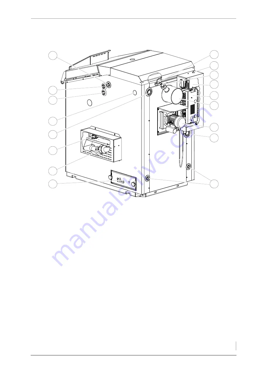
3 Mode of operation – Overview
15
R
EAR
AND
SIDE
VIEW
OF
HDG E
URO
30/40/45/50
1 Flue gas temperature sensor
2 STL release button
3 Lambda sensor
4 EM4 expansion module (optional)
5 Central module
6 Flue pipe connection 180 mm
7 Flue gas fan
8 Return connection (DN 32 inside thread)
9 Filling/draining connection (DN 15 IG)
10 Fly ash door
11 Ignition fan (only in connection with HDG automatic ignition)
12 Differential pressure switch (only in connection with HDG
automatic ignition)
13 Supply connection (DN 32 inside thread)
14 Immersion sleeve cover cap for flow/return and STL sensors
15 Safety heat exchanger outlet (DN 20, inside thread)
16 Safety heat exchanger inlet (DN 20, inside thread)
17 Connection of immersion sleeve for thermal safety device (DN 15
inside thread)
Figure 3/3 - Rear and side view of HDG Euro 30/40/45/50
14
15
16
17
8
6
5
3
1
7
9
2
13
12
11
4
10


