6 Using the heating system – Structure of the menus
136
9 B
UFFER
TANK
10 H
EATING
CIRCUIT
CCT1
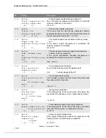
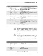
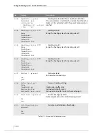
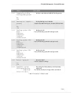
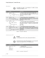
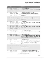
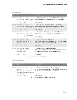
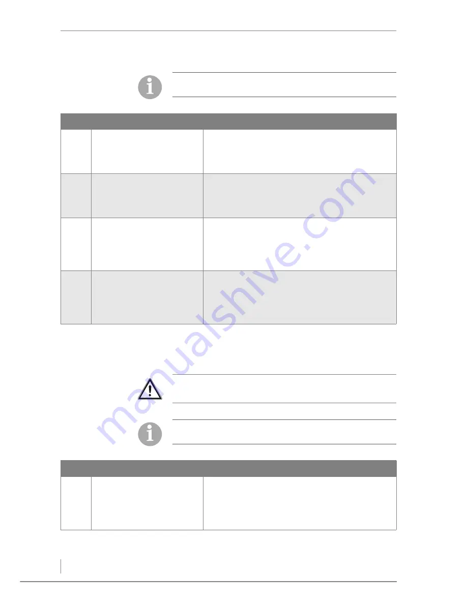
The buffer tank group is only displayed if a buffer has been
configured
parameter 8-02
.
No.
Display
Description
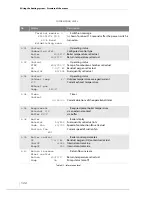
9-02
Buffer tank
Buffer maximum
(end of heating)
( 70)
70°
•
Maximum temperature at bottom of buffer tank
After reaching the preset temperature at the lower buffer
tank sensor, the boiler is turned off.
(20 - 90 °C)
9-03
Buffer tank
Buffer minimum
(start heating)
( 60)
60°
•
Minimum temperature at top of buffer tank
After reaching the preset temperature at the upper buffer
tank sensor, the boiler is started.
(20 - 90 °C)
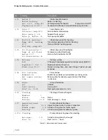
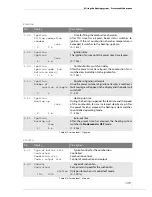
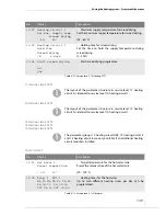
9-04
Buffer tank
Max. upper buffer
temp.
(stop heating)
( 90)
90°
•
Maximum temperature at top of buffer tank
After reaching the preset temperature at the upper buffer
tank sensor, the boiler is switched off using the safety
switch-off.
(40 - 100 °C)
9-05
Buffer tank
Preset boiler temp.
when
heating the buffer
( 80)
80°
•
Preset boiler temperature to heat the buffer
After reaching the preset minimum buffer temperature
parameter 9-03
the boiler is supplied with its target
temperature.
(50 - 90 °C)
Table 6/11 - Service level / 9 Buffer tank
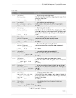
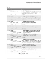
Warning!
Low temperature circuits must be switched via thermostats.
To display the menu windows from
parameter 10-18
onwards,
Floor heating
must be set as the heating system.
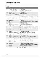
No.
Display
Description
10-01
Operation CCT1
Off
Reduction
Heating
Automatic
•
Operating status
Set the heating circuit operating status.
Table 6/12 - Service level / 10 Heating CCT1
Summary of Contents for Pelletmaster 15
Page 1: ...hdg bavaria com HDG Pelletmaster 15 25 Operation Manual V 03 08 2008 ...
Page 2: ......
Page 170: ...170 HDG Pelletmaster 15 25 V 03 en HDG Bavaria GmbH 08 2008 ...
Page 171: ......

