background image

7 Cleaning and maintaining the heating system – Procedure

148

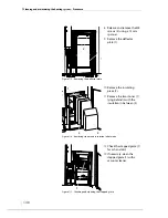
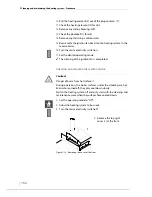
8.

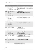
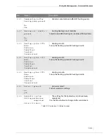
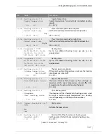
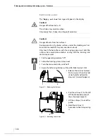
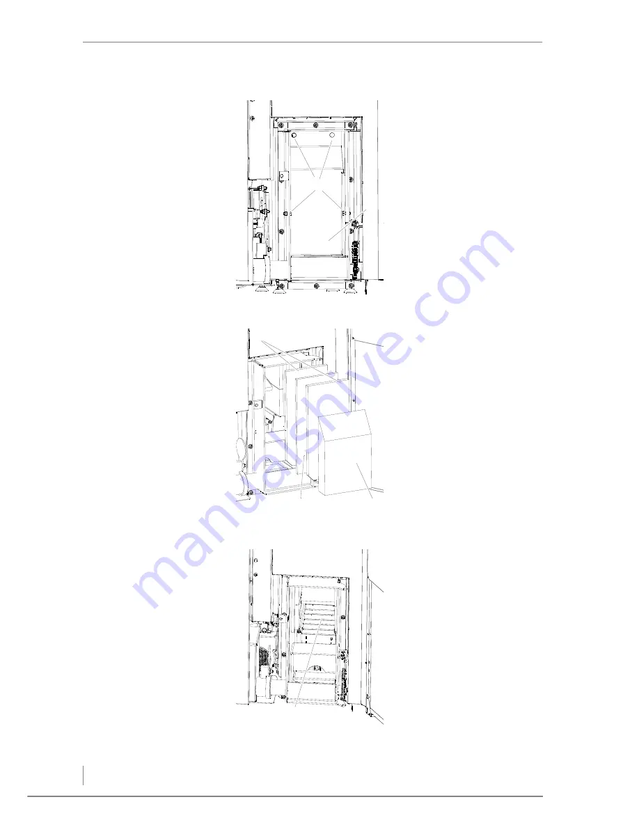
Release and remove the M8 
screws (2) using a 13 mm 
spanner.

9.

Remove the deflector 
plate (1).

Figure 7/5 - Removing the deflector plate

2

1

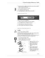
10.

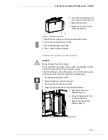
Remove the insulating 
piece (2).

11.

Remove the two stones (1) 
lying behind it with the 
insulation in between (3).

Figure 7/6 - Removing stones and insulation in between

1

2

3

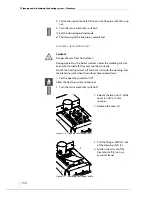
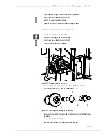
12.

Check the stepped grate (1) 
for ash and dirt.

13.

If necessary, clean the 
stepped grate (1) with a 
vacuum cleaner.

Figure 7/7 - Checking and cleaning the stepped grate

1

Summary of Contents for Pelletmaster 15

Page 1: ...hdg bavaria com HDG Pelletmaster 15 25 Operation Manual V 03 08 2008 ...

Page 2: ......

Page 3: ...ster 15 25 side view 15 3 2 Functional description 16 Combustion process 16 HDG Pelletronic 17 Injection and extraction nozzles 18 Delivery system 18 Vacuum delivery system 18 HDG Hydronic 18 HDG Hydronic control functions 19 3 3 Technical data 25 3 4 Fuel quality requirements 26 Permissible fuel 26 Recommended wood pellets 27 4 Planning and installation 28 4 1 Planning the heating system 28 Space...

Page 4: ...5 Installing the control unit 65 Installing the sensors 66 Hydraulic systems 69 4 6 Pellet bunker 69 Installing the injection and extraction nozzles 69 Installing the door rails 70 Installing the pellet anti shatter protective mat 71 Installing door contact switches 71 Installing the sloping floor 71 4 7 Delivery and vacuum delivery system 73 4 8 Electrical system 78 4 9 Water 78 4 10 HDG hydrauli...

Page 5: ...Performing the chimney sweep test 118 Before the measurement 119 During the measurement 119 After the measurement 120 6 10 Structure of the menus 120 Available levels 120 Contents of the levels 121 Information level 122 Customer and service levels 125 7 Cleaning and maintaining the heating system 144 7 1 Cleaning and maintenance schedule 144 7 2 Procedure 145 Emptying the ash box 146 Checking and ...

Page 6: ... Pelletmaster 15 25 Content 6 9 Notes on dismantling and disposal 166 9 1 Dismantling 166 9 2 Disposal 167 10 Warranty 168 10 1 Scope 168 10 2 Conditions 168 10 3 Warranty exclusions 168 11 EC Declaration of Conformity 169 ...

Page 7: ...rrect at the time of going to press All details in these instructions on standards regulations and worksheets should be checked before use and should be compared with the regulations applying locally at the site where the boiler is installed We reserve the right to make changes which may then deviate from the technical details and illustrations in this Operation Manual COPYRIGHT Written agreement ...

Page 8: ...how to properly plan for and install the heating system 5 Commissioning the system how the heating system is to be put into initial service 6 Using the heating system how to properly operate the heating system 7 Cleaning and maintaining the heating system how to clean the heating system and who is responsible for its maintenance 8 Troubleshooting how to rectify faults in the heating system 9 Notes...

Page 9: ...g system regulator for controlling the hydraulic systems HDG Pelletmaster 15 25 Boiler for burning wood pellets HDG Pelletronic Electronic control of the boiler Heating system Comprised of the boiler and relevant accessories Pellet vacuum container A container which supplies pellets to be burnt in the boiler via the stoker worm Rotary feeder Burn back protection separates the pellet vacuum contain...

Page 10: ...ety fixed immediately PROPER AND IMPROPER MANNER OF OPERATION APPLICATION OF THE HEATING SYSTEM The heating system was designed to burn wood pellets Any other application is considered improper use The manufacturer will accept no liability for any damage resulting from improper use The operator bears sole responsibility in such cases Proper use includes adherence to the installation operation and ...

Page 11: ...r has cooled down before touching uninsulated components Warning Danger of asphyxiation due to carbon monoxide If the boiler is operating carbon monoxide can be emitted through the open ash doors Do not leave the ash doors open any longer than necessary Caution Danger from suspended loads The boiler weighs over 250 kg If the boiler is dropped during transport persons can be seriously injured and t...

Page 12: ...rea Working in areas marked with this symbol can lead to serious injuries or to extensive material damage Caution Hand injuries can occur Working in areas marked with this symbol can lead to hand injuries Caution Hot surfaces Working in areas marked with this symbol can lead to burns Caution Danger of fire Working in areas marked with this symbol can lead to a fire Caution Frost danger Work on loc...

Page 13: ...em is required to read the Operation Manual prior to beginning work particularly the chapter 2 Safety instructions This especially applies to persons who only occasionally work on the heating system e g when cleaning or servicing it The Operation Manual must always be kept readily accessible at the heating system s installation site ...

Page 14: ...ew HDG PELLETMASTER 15 25 FRONT VIEW 1 HDG Pelletronic control unit 2 Flue pipe connection 3 Tubular heat exchanger 4 Cleaning turbulators 5 Combustion chamber 6 Control cabinet with power switch 7 Ash box Figure 3 1 HDG Pelletmaster 15 25 front side 2 3 6 7 5 4 1 ...

Page 15: ... vacuum container 3 Cleaning shaft lid with suction fan 4 Combustion chamber door 5 Ash removal 6 Stepped grate 7 Combustion fan 8 Pressure equalisation hoses 9 Ignition fan 10 Feed system Figure 3 2 HDG Pelletmaster 15 25 side view 4 5 8 6 3 2 7 9 1 2 4 5 8 6 3 2 7 9 1 2 5 6 9 7 4 3 8 10 2 1 ...

Page 16: ...ation 7 HDG Hydronic option 8 Vacuum delivery system 9 HDG Pelletmaster 15 25 boiler with HDG Pelletronic COMBUSTION PROCESS In the HDG Pelletmaster 15 25 boiler the pellets introduced into the combustion chamber are automatically ignited with an electrical ignition fan To avoid the grating from slagging up and to ensure ash removal occurs the grating is moved at intervals The ash and fly ash prod...

Page 17: ...Pelletronic system and call up information on the current process If the HDG Pelletronic signals a demand for more heat the pellet system automatically changes to Fill mode and the combustion chamber is filled with pellets Once the desired boiler temperature has been reached i e the need for heat has been met the heating system changes to Burn out mode and subsequently to the operating status No d...

Page 18: ...led through the HDG Pelletronic VACUUM DELIVERY SYSTEM The vacuum delivery system links the transfer station with the pellet vacuum container for the HDG Pelletmaster 15 25 boiler This vacuum delivery system transports the pellets from the transfer station to the vacuum container in the boiler This process is monitored by sensors and using the HDG Pelletronic can be limited to various times of day...

Page 19: ...ter leaving the boiler that the heating circuit supply temperature of the water is 67 C If an indoor thermostat unit is also connected the comparison between the preset and the actual room temperature and the room influence factor are also included in the calculation of the required water temperature leaving the boiler The temperature difference is multiplied by the room influence factor and is th...

Page 20: ...aded and a characteristic heating curve allocated Floor heating If this heating system is selected the corresponding parameters are calculated for a flatter characteristic heating curve and a lower laying temperature With this heating system you also have the option of activating a screed drying programme Constant This system operates independently from the outdoor temperature and maintains a cons...

Page 21: ... every 7 days to help prevent the pumps from seizing HOT WATER Depending on the installed hydraulic system the hot water supply can be delivered via a combination buffer tank or via an external hot water tank Only if a hydraulic system is installed with a hot water tank must the following points be considered For hot water a weekly programme two heating periods per day can be selected Only during ...

Page 22: ...oint No commands are sent to the solar heating pump and sensors are ignored SOLAR HEATING OF THE HOT WATER TANK The solar heating pump is driven at a controlled speed taking into account the temperature difference Collector temp to hot water tank lower sensor The temperature of the solar collector must exceed the Hot water lower sensor temperature by the solar hysteresis value for solar heating to...

Page 23: ...speed before then being adjusted to between the minimum and maximum pump speed DISTRICT HEATING CONNECTION Operating with district heating is very similar to heating hot water A measurement of the temperature difference between the heat source and the district heating transfer station is used to activate the district heating pump If operated without a buffer the boiler supply temperature is used a...

Page 24: ...er temp it switches off restarting when it has cooled down by the amount of the oil fired boiler hysteresis If two different enable temperatures have been specified for hot water and for heating circuits and if there is no demand on the hot water tank the oil fired boiler will only start once the temperature has fallen below the enable temperature for the heating circuits If there is no demand on ...

Page 25: ...ower 160 C 80 C 180 C 95 C Exhaust mass flow at nominal thermal power minimum thermal power 0 0100 kg s 0 0038 kg s 0 0176 kg s 0 0079 kg s Required feed pressure 12 Pa Diameter of flue pipe connection 130 mm 150 mm Height of flue pipe connection 1614 mm Supply and return connections 1 BSP DN 25 IG Emptying 1 2 BSP DN 15 IG Water side resistance at nominal thermal power Δ t 10 K Δ t 20 K 7 hPa 2 h...

Page 26: ...rnal monitoring and the labelling DINPLUS The certification to DINplus combines the two previously mentioned standards taking the stricter value in each case The certification procedure is carried out at the pellet manufacturer by a testing institute approved by DIN Certco Independent tests are made at regular intervals so that the quality of the pellets can be ensured Standard DIN 51731 ÖNORM M 7...

Page 27: ...ith a diameter of 6 8 mm and a length of 10 30 mm ideally certified according to DINplus Other requirements on the fuel result from either the German standard DIN 51731 or from the Austrian standard ÖNORM 7135 Pay particular attention to the pellet quality both when ordering and upon delivery Use pellets tested according to DINplus DIN 51731 or ÖNORM M 7135 ...

Page 28: ...e heating system SPACE REQUIREMENTS AND MINIMUM SPACING 1 Boiler room 2 Pellet bunker A Length 130 450 cm B Width min 185 cm C min 30 cm D min 30 cm E 89 cm F min length 250 cm G min 100 cm H 94 cm I 45 cm J min width 160 cm K min 60 cm Figure 4 1 Room sizes and minimum spacing 1 2 A B F J K D C G I H E ...

Page 29: ...ly the limit values of DIN 4109 Soundproofing in building construction are not to be exceeded More detailed information can be found in the respective ordinances of the countries and states PELLET BUNKER DIMENSIONS The size of the pellet bunker depends on the building s annual fuel requirement The thermal load is the main criterion here which will be determined by a heating engineer Caution Buildi...

Page 30: ...9 m3 bunker space Rule of thumb 1 kW thermal load 0 9 m3 total storage space including empty space of that 2 3 can actually be used to store pellets Due to the sloping intermediate floor and due to the space required for delivery of the pellets injection and extraction nozzles only about 2 3 of the total space available can actually be used Example For a home with a thermal load of 18 kW the follo...

Page 31: ...wall 5 PVC pipe Ø 150 mm supplied by customer 6 Coupling nozzle Storz A system Ø 100 mm with cap A Spacing to ceiling approx 20 cm Both nozzles must be properly earthed equipotential bonding The injection and extraction nozzles are installed on the narrow side just underneath the ceiling The injection nozzle should be in the middle of the space to ensure even filling The passages through the wall ...

Page 32: ...ing 150 cm2 5 Auger pipe in wall passage encased in mineral wool 6 Delivery auger 7 Sloping floor 8 Outer wall 9 Injection nozzle A Width of light well at least 60 cm Figure 4 4 Pellet anti shatter protective mat 1 A 3 2 9 5 6 7 8 4 The light well must be designed so that the tanker s delivery hose can easily be connected and disconnected ...

Page 33: ...over 50 cm 1 Pellet anti shatter protective mat A approx 10 cm B over 50 cm Spacing between the injection and extraction nozzles under 50 cm 1 Pellet anti shatter protective mat A min 50 cm B under 50 cm C approx 10 cm Figure 4 5 Injection and extraction nozzles variant 1 1 B A Figure 4 6 Injection and extraction nozzles variant 2 1 C A B ...

Page 34: ...passage through the wall normally has to be made in the wall between the boiler room and the pellet bunker Its position should be as central as possible The passage should be 25 cm wide and 28 cm high When installed the lowest point of the sloping floor panels should be at least 5 5 cm above the level of the floor in the boiler room Figure 4 7 Injection and extraction nozzles variant 3 1 A Positio...

Page 35: ...g wall thicknesses have proved adequate Medium weight vertically perforated brick 11 5 cm plastered on both sides Solid concrete 10 cm steel reinforced Aerated concrete 11 5 cm plastered on both sides Wooden framed wall approx 12 cm thick beams with planking on both sides made of 15 20 mm timber Beam spacing approx 62 5 cm The conditions for proper design include a wall length of max 5 m and a hei...

Page 36: ...n the door to the pellet bunker wooden boards must be fitted on the inside at least 3 cm tongue groove design if possible so that the pellets can t press against the door ALTERNATIVE PELLET STORAGE OPTIONS STORAGE IN A BURIED TANK An option for storing the pellets outside of the building to keep them dry and dust free is the use of a tank which can be buried in the garden Figure 4 9 Access to the ...

Page 37: ...lt free and economical operation As when partially loaded the flue temperature may lie below 100 C a chimney flue is required which meets class 1 requirements If this is not the case please contact our service department Another essential criterion is to achieve the correct conveying pressure This depends on three major factors CHIMNEY CHARACTERISTICS The requirements for minimising the draught lo...

Page 38: ...ount the following factors Location of the house Surrounding hills slopes Wind direction Location of the chimney in the roof The opening of the chimney must be at least 0 5 m above the highest edge of roofs with a slope of more than 20 or at least 1 0 m higher than roof surfaces which slope at 20 or less The effective height of a chimney is measured from the entrance into the flue to the end of th...

Page 39: ...f possible without bends take particular care in older buildings All of the cleaning and measurement hatches on the chimney must be tightly sealed To reduce the entry of additional cold air only one heat producer should be attached to each chimney ELECTRICAL SYSTEM The terms of 2006 95 EC low voltage guidelines must be followed for the electrical connections to the system No electrical installatio...

Page 40: ...r the circulation pump on a bright metal part of the supply line BUFFER TANK SENSOR AND HOT WATER SENSOR The temperature sensors are immersion sensors with a moulded cable and serve to measure the temperature of the buffer tank and the hot water tank INDOOR THERMOSTAT UNIT ROOM SENSOR With the room sensor the preset room temperature can be altered by 2 3 C A selection switch allows the operating s...

Page 41: ...gnition It is however highly recommended to use a buffer tank even with automatic boiler systems The size of the buffer tank depends on the nominal thermal power of the boiler and on the thermal requirement of the building As a guide the recommended value of 20 litres per kW boiler output can be used An advantage of using a buffer tank lies in the lower operating hours of the system and fewer star...

Page 42: ... AND FLUE SIDE CONNECTIONS FRONT VIEW 1 Connection of immersion sleeve extinguishing fittings DN 15 mm internal thread 2 Connection to extinguishing equipment DN 20 mm external thread A 1028 mm B 752 mm C 659 mm D 936 mm Figure 4 13 HDG Pelletmaster front view C B A 1 2 D ...

Page 43: ...ction 1 BSP DN 25 internal thread 3 Immersion sleeve for the supply temperature sensor STB 4 Connection nozzles for suction turbine pellet vacuum container 5 Connection for filling emptying 1 2 BSP DN 15 A 122 mm B 183 mm C 49 mm D 118 mm E 1378 mm F 347 mm G 104 5 mm Figure 4 14 HDG Pelletmaster Rear view E F G A B C D 1 2 3 4 5 ...

Page 44: ...IEW 1 Immersion sleeve return temperature sensor 2 Flue pipe connection A 251 mm B 166 mm C 1625 mm D 1378 mm INSTALLATION DIMENSION Dimensions without cladding as delivered 370 mm x 790 mm x 1450 mm Figure 4 15 HDG Pelletmaster Right side view A B C D 1 2 ...

Page 45: ...25 Unclad boiler body HDG Pelletmaster 15 25 Boiler cladding Control cabinet and electrical parts DELIVERY AND VACUUM DELIVERY SYSTEM Optional extension module for the delivery system 1 5 m Pellet anti shatter protective mat Optional extension module for the delivery system 1 0 m Basic delivery system module TBZ 70 feed system with pellet vacuum container and suction turbine Transfer station with ...

Page 46: ...rsons the heating system can be damaged and persons may be injured due to secondary damage Only allow authorised specialists to perform the installation Danger Danger from electrical current or voltage Switch off the power supply and isolate the mains cable to the heating system during the installation Danger Dust explosion due to build up of static charge Only qualified electricians certified acc...

Page 47: ...ide 10 Use the plastic feet to align the boiler horizontally The boiler has been set up Caution Danger from suspended loads The boiler weighs over 250 kg If the boiler is dropped during transport persons can be seriously injured and the boiler can be damaged Make sure that you use appropriate lifting gear when installing the boiler 6 Tilt the boiler slightly to the left 7 Screw on the plastic feet...

Page 48: ...the spring clip 3 The supply temperature sensor and the capillary sensor of the safety temperature limiter have been installed RETURN TEMPERATURE SENSOR Figure 4 17 Installing the supply sensors 1 3 2 4 The capillary sensor is found upon delivery in the control cabinet See Figure 4 23 Installing the control cabinet 4 Insert the return temperature sensor 1 with the blue mark in the right hand side ...

Page 49: ...ing a 13 mm spanner 2 Adjust the supporting foot 6 3 Bolt the combustion fan 5 onto the air distributor box 4 with intermediary seal with four 5 mm hexagon socket screws The feed system and combustion fan have been installed INSTALLING THE IGNITION FAN 1 Push the ignition fan 1 into its retaining tube 2 The ignition fan has been installed Figure 4 19 Installing the feed system and combustion fan 1...

Page 50: ...the long pressure equalisation hose 3 with the hose clip 1 4 Slide the hose clip 1 onto the short pressure equalisation hose 3 5 Insert the short pressure equalisation hose 3 onto the connection nozzle on the rotary feeder 2 6 Fasten the short pressure equalisation hose 3 with the hose clip 1 The pressure equalisation hoses have been connected Figure 4 21 Connecting the long pressure equalisation ...

Page 51: ...ler using a 13 mm spanner 3 Insert the green and yellow earth cable 2 against the upper right stud bolt 3 and screw it tight The control cabinet has been installed ATTACHING THE BOILER CLADDING FRONT BOILER CLADDING 1 Remove the pre mounted flat headed screws of the front cladding 2 from the boiler body Figure 4 23 Installing the control cabinet 2 4 3 1 Figure 4 24 Attaching the front boiler cladd...

Page 52: ...ulation 3 of the front cladding so that it doesn t contact any moving parts of the automatic cleaning system 5 Mount the front cladding on the boiler with the flat headed screws 6 Guide the cable 3 of the automatic cleaning system through the upper slot 1 and into the control cabinet 2 7 Mount the cover of the cleaning system motor back onto the front cladding The front cladding has been attached ...

Page 53: ...n the rear side of the boiler 3 Mount the rear cladding 1 on the boiler with the flat headed screws The rear cladding has been attached RIGHT HAND BOILER CLADDING 1 Hook the right hand cladding 1 into the already pre mounted shaped studs on the front and rear cladding of the boiler The right hand cladding has been attached Figure 4 27 Attaching the rear cladding 1 Figure 4 28 Attaching the right h...

Page 54: ...left hand cladding panel next to the boiler 2 Remove the cover plate for the cable channel 2 of the cladding on the left side 3 Feed the cables 1 for the sensors into the cable channel Figure 4 29 Attaching the left hand cladding 1 2 Figure 4 30 Laying the cables 1 Figure 4 31 Laying the cables 2 1 3 ...

Page 55: ...ng into the already pre mounted shaped studs on the front and rear cladding of the boiler 6 Firmly bolt the cover plate of the boiler cable channel 3 to the left hand cladding of the boiler The left cladding has been installed INSTALLING THE PELLET VACUUM CONTAINER 1 Remove the cover from the vacuum pellet container When delivered the lid of the pellet vacuum container is fitted the wrong way roun...

Page 56: ...the front lock nut of the enclosed fill level sensor 5 Insert the fill level sensor 1 in the opening provided for this in the pellet vacuum container 2 6 Mount the fill level sensor in the pellet vacuum container so that the thread protrudes at least 1 5 cm into the container 7 Counter the locking nut 3 Figure 4 33 Installing the pellet vacuum container 1 2 Figure 4 34 Mounting the fill level sens...

Page 57: ...urbine and the fill level sensor in the cable channel 2 The pellet vacuum container has been installed INSTALLING THE WIRING IN THE CONTROL CABINET 1 Connect the plug on the control cabinet 1 See HDG Hydronic circuit diagram Figure 4 35 Installing the pellet vacuum container 2 1 Connect the thermal safety device which is used here as an extinguisher with a suitable flexible hose Figure 4 36 Instal...

Page 58: ...he rear cladding 2 together using the M5 screws and wing nuts 2 Insert the rear plastic foot 3 3 Hook the rear cladding onto both shaped studs on the left hand cladding and fix in place with the M5 screw 1 The cladding for the technical components has been attached Note the connection of the RC element Figure 4 37 Attaching the cladding for the technical components 1 2 3 Figure 4 38 Attaching the ...

Page 59: ...ATTACHING THE TECHNICAL COMPONENTS DOOR 1 Place the door frame 1 on the stud bolt 2 of the plastic foot 2 Insert the stud bolt of the plastic foot 2 through the front hole of the technical components 1 Figure 4 39 Attaching the plastic feet 1 2 Figure 4 40 Attaching the door frame 3 1 2 ...

Page 60: ... 17 mm nut from the stud bolt 1 on the front part of the boiler cladding 5 Attach the lid brace 2 to the stud bolt 1 on the front part of the boiler cladding and refit the nut 6 Unscrew the 17 mm nut of the plastic foot 2 front left on the boiler 7 Place the bracing and support plate 1 on the stud bolts of the plastic feet 2 3 Figure 4 41 Attaching the lid brace 1 2 Figure 4 42 Attaching the lower...

Page 61: ...M10 nuts 9 Insert the ash box 1 in the bracing and support plate 3 and slide the ash box on the connection of the auger channel 2 10 Close the clamp lock 4 11 Screw the door to the door frame The ash box and the door of the technical components have been installed FITTING THE COVERS 1 Place the right upper cover 1 on the rear of the boiler Figure 4 43 Attaching the lower brace 2 3 1 4 Figure 4 44 ...

Page 62: ...urn hose 1 2 Connect the return hose 1 to the suction turbine 3 3 Fasten the return hose 1 with the hose clip 2 on the connection nozzle for the suction turbine 3 4 Connect the suction hose 5 as previously described to the connection nozzle 4 of the pellet vacuum container The return hose and the suction hose have now been attached on the boiler side Figure 4 45 Fitting the right front cover 1 Fig...

Page 63: ...OMPONENTS 1 Undo the 17 mm nut 1 on the lid brace 2 2 Connect the cover of the technical components with the bearer of the control panel 3 Attach the connection cable plug 2 to the control unit 3 Figure 4 47 Fitting the left cover 1 2 Figure 4 48 Fitting the cover to the technical components 2 3 1 ...

Page 64: ...id brace 1 using a 17 mm spanner The cover claddings have been fitted CONNECTING THE CHIMNEY 1 Connect the flue pipe to the chimney connection 2 Make sure that the connecting piece does not protrude into the chimney 3 Seal the connection to the chimney with highly fireproof silicone or with a suitable mortar The boiler has been connected to the chimney Figure 4 49 Fitting the cover to the technica...

Page 65: ...age Switch off the power supply and isolate the mains cable to the heating system during the installation Caution Material damage due to static discharge Electronic components can be damaged by static discharge Do not touch any electronic components during the installation The bus cable between the HDG Pelletronic and HDG Hydronic must be protected from inductive coupling from 230 V wires Only use...

Page 66: ...pter Take great care that you use the correct sensors contact sensors immersion sensors outdoor sensors since if incorrectly applied error messages and resulting malfunctions in the control system can then occur All of the sensors in the HDG Hydronic are PT 1000 sensors Temperature PT 1000 50 C 803 10 Ohm 40 C 842 70 Ohm 30 C 882 20 Ohm 20 C 921 60 Ohm 10 C 960 60 Ohm 0 C 1000 00 Ohm 10 C 1039 00 ...

Page 67: ...ircuit sensor 1 to the pipe flush with its surface using the supplied hose clip 2 See section 4 2 Connections in this chapter 1 Install the outdoor sensor at its intended position on the wall with its cable outlet downwards See section 4 2 Connections in this chapter Figure 4 52 Outdoor sensor Figure 4 53 Heating circuit sensor 2 1 ...

Page 68: ...anks are not bent 4 Carefully insert the buffer and hot water tank sensors into the immersion sleeves INSTALLING A ROOM SENSOR Figure 4 54 Sensors for buffer and hot water tanks 1 Fasten the room sensor at its intended position on the wall See section 4 2 Connections in this chapter Figure 4 55 Room sensor Figure 4 56 Room sensor without cover ...

Page 69: ... suitable for the on site conditions 3 Earth the injection nozzle 4 Install the extraction nozzle as just described 5 Earth the extraction nozzle The injection and extraction nozzles have been installed Danger Dust explosion due to build up of static charge Only qualified electricians certified according to TRBS 1203 1 may perform work on electrical systems in areas at risk of explosion On the con...

Page 70: ...ve been installed INSTALLING THE DOOR RAILS 1 Saw the door rails 1 if necessary down to the required length 2 Bolt on the door rails 1 at a sufficient distance to the ceiling at least 1 5 times the height of the boards used at the sides of the access hatch on the inner wall 2 of the pellet bunker The door rails have been installed Figure 4 58 Installing extension pipes 1 Figure 4 59 Earthing exten...

Page 71: ...n 4 1 Planning the heating system in this chapter The following details are recommendations which have been proven in practice HDG Bavaria GmbH accepts no liability and will provide no guarantee for the construction of the sloping floor Recommended components Bearing beams Squared timber 80 x 50 mm Screws 8 x 140 mm Sloping floor panels with a smooth low friction surface Coated wooden boards at le...

Page 72: ...as shown in Fig 4 61 The sloping floor supports have been installed INSTALLING THE BEARING BEAMS 3 Bolt the bearing beams 1 short side up onto the sloping floor supports 2 4 To provide additional support for the bearing beams bolt additional squared timbers to the walls 3 The bearing beams have been installed Figure 4 61 Installing the sloping floor supports B A 1 Figure 4 62 Installing the bearin...

Page 73: ...ge 1 through the hole in the wall When installed the lowest point of the sloping floor panels must be at least 5 5 cm above the top edge of the finished floor in the room where the boiler is installed Please note that if the level of the pellet bunker and that of room where the boiler is installed are different the clearance between the intersection of the sloping floor panels and the boiler room ...

Page 74: ...wall The transfer station has been installed INSTALLING THE DELIVERY AUGER 4 Pull the feather key 1 out of the delivery auger 2 5 From the pellet bunker side slide the delivery auger 2 out through the transfer station 1 6 Insert the feather key back in the delivery auger The delivery auger has been installed Figure 4 65 Removing the feather key 1 2 Figure 4 66 Installing the delivery auger 1 2 ...

Page 75: ...en installed on the delivery auger INSTALLING THE PRESSURE RELIEF PLATE 10 Position the pressure relief plate 2 over the delivery auger 3 11 The hole 5 for the bearing unit must be at the end of the delivery auger 3 12 Ensure that the pressure relief plate 2 is flush with the transfer station 1 13 Screw the pressure relief plate 2 to the sloping floor 4 using the chipboard screws The pressure reli...

Page 76: ... The bearing unit has been fixed in place The delivery auger has been installed INSTALLING THE EXTENSION MODULE 16 Slide the delivery auger for the extension module 4 onto the pin of the basic module 1 17 The feather key must fit into the slot 18 Install the bearing unit 3 and the pressure relief plate 2 as described above The extension module has been installed Figure 4 69 Fastening the bearing u...

Page 77: ...motor and the delivery system have been installed CONNECTING THE SUCTION AND RETURN HOSES 1 Separate out about 10 cm of the wire worked into the suction hose 2 at the transfer station end 2 Slide the hose clip 3 over the suction hose 2 Figure 4 71 Installing the motor 1 2 3 4 5 Figure 4 72 Connecting the suction hose 2 1 4 3 5 On the lower right side of the transfer station there is an arrow which...

Page 78: ...ter 3 Mode of operation section 3 3 Technical data 4 9 Water The heating system must be filled with water in accordance with VDI guideline 2035 Avoiding damage in hot water heating systems Before putting the system into operation the pressure of the membrane expansion container must be adjusted for the conditions in the heating system and in the building After putting the system into operation hea...

Page 79: ...boards A brief description of the menu system is also provided in table form for the selection of the respective hydraulic diagram Figure 4 73 Hydraulic system 0 P e lle t m a s t e r M Bb OT Bt ST RT HDG Pelletronic Connection OTS Outdoor temperature sensor 40 41 ST Supply temperature sensor boiler temperature 48 49 RT Return temperature sensor 46 47 Bt Buffer top sensor 44 45 Bb Buffer bottom se...

Page 80: ...tion HDG hydraulic systems 80 No Description 8 01 Select hydraulic system 0 8 02 Select buffer type 8 12 Option of activating an additional heating circuit module 8 00 The settings for the hydraulic system have been completed ...

Page 81: ...m 1B P e lle t m a s t e r M M M M M A4 A5 A7 8 A1 F5 Bb F4 Bt ST A9 10 RT F10 OT CCT1 CCT2 HDG Pelletronic Connection OT S Outdoor temperature sensor 40 41 ST Supply temperature sensor boiler temperature 48 49 RT Return temperature sensor 46 47 Bt Buffer top sensor 44 45 Bb Buffer bottom sensor 42 43 ...

Page 82: ...8 Heating circuit mixer CCT1 closed H32 F9 not assigned A9 Heating circuit mixer CCT2 open H29 F10 Solar collector temperature H19 H20 A10 Heating circuit mixer CCT2 closed H30 No Description Notes 8 01 Select hydraulic system 1 8 02 Select buffer type 8 04 Set the heating system for heating circuit 1 8 05 Set the heating system for heating circuit 2 8 08 For solar heating settings 8 10 Option of ...

Page 83: ... lle t m a s t e r M M M M M M M Bt Bb RT ST OT A3 F9 A9 10 A5 F5 A1 2 A4 F4 A7 8 CCT1 CCT2 CCT3 HDG Pelletronic Connection OT S Outdoor temperature sensor 40 41 ST Supply temperature sensor boiler temperature 48 49 RT Return temperature sensor 46 47 Bt Buffer top sensor 44 45 Bb Buffer bottom sensor 42 43 ...

Page 84: ...d A6 not assigned F7 not assigned A7 Heating circuit mixer CCT1 open H31 F8 not assigned A8 Heating circuit mixer CCT1 closed H32 F9 Supply CCT3 H17 H18 A9 Heating circuit mixer CCT2 open H29 F10 not assigned A10 Heating circuit mixer CCT2 closed H30 No Description Notes 8 01 Select hydraulic system 2 8 02 Select buffer type 8 04 Set the heating system for heating circuit 1 8 05 Set the heating sy...

Page 85: ...Hydraulic system 3 Bt Bb RT ST OT A9 10 A5 F5 F4 A7 8 F9 A4 A3 CCT1 CCT2 DH HDG Pelletronic Connection OT S Outdoor temperature sensor 40 41 ST Supply temperature sensor boiler temperature 48 49 RT Return temperature sensor 46 47 Bt Buffer top sensor 44 45 Bb Buffer bottom sensor 42 43 ...

Page 86: ... A7 Heating circuit mixer CCT1 open H31 F8 not assigned A8 Heating circuit mixer CCT1 closed H32 F9 District heating temperature H17 H18 A9 Heating circuit mixer CCT2 open H29 F10 not assigned A10 Heating circuit mixer CCT2 closed H30 No Description Notes 8 01 Select hydraulic system 3 8 02 Select buffer type 8 04 Set the heating system for heating circuit 1 8 05 Set the heating system for heating...

Page 87: ...e lle t m a s t e r M M M M M M Bt Bb RT ST OT A9 10 A5 F5 F4 A7 8 F3 A4 A2 A3 A1 F2 F10 CCT1 CCT2 HDG Pelletronic Connection OT S Outdoor temperature sensor 40 41 ST Supply temperature sensor boiler temperature 48 49 RT Return temperature sensor 46 47 Bt Buffer top sensor 44 45 Bb Buffer bottom sensor 42 43 ...

Page 88: ...er CCT1 open H31 F8 not assigned A8 Heating circuit mixer CCT1 closed H32 F9 not assigned A9 Heating circuit mixer CCT2 open H29 F10 Solar collector temperature H19 H20 A10 Heating circuit mixer CCT2 closed H30 No Description Notes 8 01 Activate hydraulic system 4 8 02 Select buffer type 8 04 Set the heating system for heating circuit 1 8 05 Set the heating system for heating circuit 2 8 07 Option...

Page 89: ...S Bt Bb RT ST OT A9 10 A5 F5 F4 A7 8 F3 A4 A2 A3 A6 F2 F10 CCT1 CCT2 A1 X HDG Pelletronic Connection OT S Outdoor temperature sensor 40 41 ST Supply temperature sensor boiler temperature 48 49 RT Return temperature sensor 46 47 Bt Buffer top sensor 44 45 Bb Buffer bottom sensor 42 43 X Plate heat exchanger ...

Page 90: ...cuit mixer CCT1 open H31 F8 not assigned A8 Heating circuit mixer CCT1 closed H32 F9 not assigned A9 Heating circuit mixer CCT2 open H29 F10 Solar collector temperature H19 H20 A10 Heating circuit mixer CCT2 closed H30 No Description Notes 8 01 Activate hydraulic system 4 8 02 Select buffer type 8 04 Set the heating system for heating circuit 1 8 05 Set the heating system for heating circuit 2 8 0...

Page 91: ...tm a s t e r M M M M M M M M Bt Bb RT ST OT A9 10 A5 F5 F4 A7 8 F3 A4 A3 A1 F2 F10 F9 A2 CCT1 CCT2 DH HDG Pelletronic Connection OT S Outdoor temperature sensor 40 41 ST Supply temperature sensor boiler temperature 48 49 RT Return temperature sensor 46 47 Bt Buffer top sensor 44 45 Bb Buffer bottom sensor 42 43 ...

Page 92: ... open H31 F8 not assigned A8 Heating circuit mixer CCT1 closed H32 F9 District heating temperature H17 H18 A9 Heating circuit mixer CCT2 open H29 F10 Solar collector temperature H19 H20 A10 Heating circuit mixer CCT2 closed H30 No Description Notes 8 01 Select hydraulic system 5 8 02 Select buffer type 8 04 Set the heating system for heating circuit 1 8 05 Set the heating system for heating circui...

Page 93: ... t m a s t e r M M M M M M M M Bt Bb RT ST OT A9 10 A5 F5 F4 A7 8 F2 A4 A3 A6 F9 A1 2 CCT1 CCT2 CCT3 HDG Pelletronic Connection OT S Outdoor temperature sensor 40 41 ST Supply temperature sensor boiler temperature 48 49 RT Return temperature sensor 46 47 Bt Buffer top sensor 44 45 Bb Buffer bottom sensor 42 43 ...

Page 94: ... H25 F7 not assigned A7 Heating circuit mixer CCT1 open H31 F8 not assigned A8 Heating circuit mixer CCT1 closed H32 F9 Supply CCT3 H17 H18 A9 Heating circuit mixer CCT2 open H29 F10 not assigned A10 Heating circuit mixer CCT2 closed H30 No Description Notes 8 01 Select hydraulic system 6 8 02 Select buffer type 8 04 Set the heating system for heating circuit 1 8 05 Set the heating system for heat...

Page 95: ...A9 10 A5 F5 F4 A7 8 F3 A4 A2 CCT1 CCT2 DH F9 A3 F10 F2 A1 X HDG Pelletronic Connection OT S Outdoor temperature sensor 40 41 ST Supply temperature sensor boiler temperature 48 49 RT Return temperature sensor 46 47 Bt not assigned Bb not assigned X Hydraulic switch ...

Page 96: ...t assigned A8 Heating circuit mixer CCT1 closed H32 F9 District heating temperature H17 H18 A9 Heating circuit mixer CCT2 open H29 F10 Solar collector temperature A10 Heating circuit mixer CCT2 closed H30 No Description Notes 8 01 Select hydraulic system 7 8 03 Heating circuit control settings for use of residual heat 8 04 Set the heating system for heating circuit 1 8 05 Set the heating system fo...

Page 97: ...T F4 A7 8 F2 A4 A3 CCT1 CCT2CCT3 F9 A1 2 X A6 A5 F5 A9 10 HDG Pelletronic Connection OT S Outdoor temperature sensor 40 41 ST Supply temperature sensor boiler temperature 48 49 RT Return temperature sensor 46 47 Bt not assigned Bb not assigned X Hydraulic switch ...

Page 98: ... A7 Heating circuit mixer CCT1 open H31 F8 not assigned A8 Heating circuit mixer CCT1 closed H32 F9 Supply CCT3 H17 H18 A9 Heating circuit mixer CCT2 open H29 F10 not assigned A10 Heating circuit mixer CCT2 closed H30 No Description Notes 8 01 Select hydraulic system 8 8 03 Heating circuit control settings for use of residual heat 8 04 Set the heating system for heating circuit 1 8 05 Set the heat...

Page 99: ... of the mains supply to the heating system switched off CHECK THE MECHANICAL ASSEMBLY Have the system components been correctly installed Have all of the mechanical components been firmly screwed together Have the combustion chamber grate and ignition fan been correctly installed CHECK THE HYDRAULIC CONNECTIONS Have the return pump and the return mixer been correctly installed Has the safety equip...

Page 100: ...on on the circuit board box been screwed to the body of the boiler BASIC SETTINGS FOR THE PRIMARY AND SECONDARY AIR SUPPLY The setting knobs to control the primary 1 and secondary 2 air supply are located behind the left cover of the HDG Pelletmaster 15 25 1 Check the settings of the control knobs 2 Adjust the setting as specified in Table 5 1 Setting of control knobs Danger Danger from electrical...

Page 101: ...e checked again 1 Press the locking button 4 and simultaneously turn the grate drive shaft 1 to the left and to the right 2 Determine the middle point of the grate drive shaft 1 by turning left and right 3 Align the grate drive shaft 1 in the middle position 4 Align the limit switch 3 vertically in the middle position with the arrow pointing toward the grate drive shaft 5 Set the reversing switch ...

Page 102: ...tched on SETTING THE BOILER OUTPUT AND DISPLAY LANGUAGE BOILER OUTPUT SETTING 1 Simultaneously press the Plus and Enter buttons The display will change to the service level The cursor is positioned on the parameter group 1 General 2 Press the Enter button 3 Press the Down button until you reach the parameter Boiler Type 1 01 4 Press the Enter button 5 Use the Plus or Minus button to select the req...

Page 103: ...o the service level 2 Using the Down button select the parameter group 8 Hydraulic system 3 Press the Enter button The display will change to the parameter Hydraulic system 8 01 The cursor flashes on zero 4 Use the Plus or Minus button to select the installed hydraulic system For an overview of the given hydraulic systems see chaper 4 Planning and installation section 4 10 HDG hydraulic systems En...

Page 104: ...nu selection CHECKING THE ACTUATORS IN MANUAL OPERATION 1 Switch to manual operating mode See chapter 6 Using the heating system section 6 6 Changing operating mode 2 Check that the following actuators work properly Delivery system h 01 Delivery system h 02 Automatic grate h 03 Grate h 04 Cleaning h 05 Stoker auger h 06 Cleaning h 06a Combustion fan h 07 Suction h 08 Ignition h 09 Return valve h 1...

Page 105: ...s displayed The current outdoor temperature is displayed 5 Select Sensor2 h 13 The current combustion chamber temperature is displayed The current temperature measured by the flue gas sensor is displayed The current residual oxygen value is displayed 6 Select Sensor3 h 14 The current temperature measured by the upper buffer sensor is displayed The current temperature measured by the lower buffer s...

Page 106: ...l display 3 Simultaneously press the Plus and Enter buttons The display changes to the service level 4 Check the basic settings for the following service parameters General Boiler Ignition Control Return Cleaning Delivery Buffer tank 5 To access the respective parameter group select the group using the Up or Down buttons 6 Confirm the selected group with the Enter button The display changes to the...

Page 107: ...ot work correctly in automatic mode the parameters in the service level will have to be adapted accordingly See chapter 6 Using the heating system section 6 10 Structure of the menus PARAMETERS FOR MANUAL OPERATION In manual operating mode additional parameters are available depending on the selected hydraulic system These are primarily used for the various mixers and pumps 1 Switch to manual oper...

Page 108: ... value to 1 with the Plus button 6 Press the Enter button The settings for the initial commissioning are saved and can be reloaded at any time if lost by calling up the parameter General 1 07 The setting of the parameters is completed Enter No Display Description 1 06 General Operating parameters save 0 0 The set operating parameters can be saved Table 5 6 Saving operating parameters Enter Enter ...

Page 109: ...for the HDG Pelletronic is on the left upper side of the HDG Pelletmaster 15 25 boiler Through the control unit you can regulate the HDG Pelletronic system and call up information on the current processes DISPLAY The display shows the selected information and parameters In section 6 10 Structure of the menus in this chapter all selectable information and parameters are listed Danger Danger from el...

Page 110: ...nter button Enables the displayed value to be changed Confirms the changed value One step forwards Mode button Select the operating mode OPERATING MODE INDICATOR The symbols show the current operating mode of the heating system The selected symbol flashes if the selected operating mode has not yet been confirmed with the Enter button The symbols show the following operating modes AUTOMATIC This mo...

Page 111: ...QUIREMENTS Before the heating system is turned on the following conditions must be met The heating system has been commissioned by authorised specialists The fuse on the power supply is switched on The mains switch on the heating system is turned off No operating mode is displayed on the control unit of the HDG Pelletronic The pellet bunker has been filled See section 6 8 Filling the pellet bunker...

Page 112: ... this chapter 1 Press the Down button The display will change to the next item of information 2 Press the Up button The display will change to the previous item of information 3 Press the Menu button more than once if necessary The standard display of i 01 is shown 6 5 Selecting and changing parameters On the HDG Pelletronic control unit various parameters can be selected and altered See section 6...

Page 113: ...rameter 6 Repeat the procedure until the parameter to be changed is shown on the display The parameter to be changed is shown on the display CHANGING PARAMETERS 7 Press the Enter button The cursor will flash underneath the first parameter The value displayed can be changed 8 Press the Plus or Minus button The value of the parameter is increased or decreased 9 Press the Up or Down button The cursor...

Page 114: ... Either Par 2 10 or 2 11 are shown in the display 5 Press the Enter button The cursor flashes underneath the first day of the week Mon The value displayed can be changed 6 Press the Plus or Minus button The weekday is hidden or displayed 7 Press the Down button The cursor flashes underneath the next weekday 8 Hide the days where no enable or reduction times are to be entered as described in step 4...

Page 115: ...o on programme 1 and two on programme 2 Select the required level as follows 1 Press the Enter button The customer level is shown on the display 2 Using the Down button select the parameter group 10 3 Press the Enter button 4 Repeatedly press the Down button until Par 10 05 or 10 06 appears in the display Either Par 10 05 or 10 06 are shown in the display 5 Press the Enter button The cursor flashe...

Page 116: ... the Mode button repeatedly until the symbol for the desired operating mode flashes The desired operating mode has been preselected 2 Press the Enter button The selected operating mode has been confirmed The symbol for the selected operating mode lights up The heating system switches to the selected operating mode 6 7 Operational statuses The heating system goes through the following states during...

Page 117: ...ol The heating system runs automatically and is controlled as configured This operating status is maintained until a change is made to a different status Burning out The preset boiler temperature has been reached The boiler has been switched off This operating status is maintained until the boiler temperature exceeds the demanded preset temperature Frost protection The mains switch is turned on Fr...

Page 118: ...hat the pellet bunker can be filled 4 After the tank is filled close the injection and extraction nozzles 5 Switch the heating system on See section 6 2 Switching the heating system on in this chapter The pellet bunker filling has been completed 6 9 Performing the chimney sweep test In Germany pellet heating systems with a power rating above 15 kW are legally required to be annually inspected by a...

Page 119: ...eselected 4 Press the Enter button The operating mode CHIMNEY SWEEP TEST has been confirmed The CHIMNEY SWEEP TEST symbol lights up The heating system switches to CHIMNEY SWEEP TEST mode If the HDG Hydronic equipment is connected all of the loads will automatically be activated to maximise the heat transfer The display will show No test yet DURING THE MEASUREMENT Please observe the following when ...

Page 120: ...y to operate the equipment are listed in the following menu structure In the display depending on the configuration of the system and the equipment installed in the heating system some parameters may not be shown as they are possibly not required for the particular installation These will only be displayed if the corresponding hydraulic diagram was selected during the commissioning process AVAILAB...

Page 121: ...anual CONTENTS OF THE LEVELS 1 General 2 Boiler 3 Ignition 4 Control 5 Return 6 Cleaning 7 Delivery system 8 Hydraulic system 9 Buffer tank 10 Heating circuit CCT1 11 Heating circuit CCT2 12 Heating circuit CCT3 16 Hot water 18 Solar 19 District heating 20 Second boiler 21 Combination heating pump The following pages show all practically available menu windows In actuality only those menu windows ...

Page 122: ...mp 6 6 C Exhaust gas temp 110 C Operating status Outdoor temperature averaged current Current exhaust temperature i 04 Times Control 00 00 00 Times Current durations of the operational states i 05 Requirement External 0 C Buffer 80 C Required preset boiler temperature via an external contact via buffer i 08 Boiler Material 50 50 Comb fan 60 70 Suction fan 80 Boiler display Fuel quantity set actual...

Page 123: ...mperature set actual Mixer status Closed Open Heating cct pump status On Off i 15 Heating circuit 4 Heating Supply 63 65 Mixer Open HCP On Information for heating circuit CCT4 Operational state of heating cct Supply temperature set actual Mixer status Closed Open Heating cct pump status On Off i 16 Heating circuit 5 Heating Supply 66 65 Mixer Open HCP On Information for heating circuit CCT5 Operat...

Page 124: ...1 full 1 Stoke time 20 30 Delivery system Fill level of intermediate pellet container empty full 0 1 Motor protection OK yes no Stoker running time until next filling of pellet vacuum container i 24 Fill container Enabled 0 1 Del auger runtime 105m Fill container Enable time enables vacuum delivery system yes no Running time for delivery auger tank will be filled in 105 min i 25 Grate off Limit sw...

Page 125: ... hours Number of grate movements forwards backwards Running time of cleaning programme i 29 Digital values IN Bit 0123456789abcdef OUT States of digital inputs and outputs Information for HDG service Date and time Tue 12 08 08 13 32 25 Date and time Weekday date Time HDG Bavaria Pellet boiler HCR Crater 2008 06 18 D FR E Software version No Display Description Table 6 2 Information level continuat...

Page 126: ...s disables emergency operation 0 1 1 06 General Operating parameters save 0 0 Save operating parameters All current settings will be saved in a separate database 0 1 1 07 General Operating parameters load 0 0 Load operating parameters All settings will be overwritten by the database 0 1 1 09 General Initial commissioning 0 0 Initial commissioning All settings will be overwritten with factory setti...

Page 127: ...the maximum preset temperature for the boiler 50 80 C 2 04 Boiler Preset temperature Increase 0 0 Increase in the preset boiler temperature To achieve the required supply temperature for the loads the boiler temperature is increased 0 10 C 2 05 Boiler preset temperature Hysteresis 10 10 Boiler hysteresis The difference between the boiler temperatures to switch on and to switch off 0 20 C 2 06 Boil...

Page 128: ...ture is exceeded the chimney sweep test is enabled 300 1000 C 2 16 Boiler Frost protection enable disable 1 1 Frost protection for the boiler To switch frost protection for the boiler on off 0 1 Caution danger of frost 2 17 Boiler Frost protection for pumps if outdoor temp below 5 5 Frost protection for pumps If the outdoor temperature falls below the preset level the pumps will be turned on 30 10...

Page 129: ...the preset number of ignition attempts is reached a fault message will appear in the display and the boiler will switch off 1 20 3 11 Ignition Heating up time 5 5 m Heating up time During the heating up period the feed rate and the speed of the combustion fan are increased step by step After the preset time has elapsed the heating system switches to controlled operating mode 1 30 m 3 16 Ignition B...

Page 130: ... target temperature for the combustion chamber at nominal load Only possible when in combustion control mode 200 1000 C No Display Description Table 6 6 Service level 4 Control Warning Falling below dew point Do not set the return temperature below 55 C No Display Description 5 02 Return Mixer total runtime 150 150 s Total runtime of return flow mixer Set the total runtime of the return flow mixer...

Page 131: ...rds Fwd wait time 15 15 s Pause time for grate moving forwards Set the time after which the grate moves backwards 0 1000 s 6 07 Cleaning Grate back Back time 3 3 s Time that the grate moves backwards Set the time that the grate moves backwards 0 500 s 6 09 Cleaning Grate back Back wait time 15 15 Pause time for backward movement of grate Set the time after which the grate moves backwards again 0 1...

Page 132: ...times On 00 00 On 00 00 Off 24 00 Off 00 00 Enable times for delivery The pellet vacuum container will be filled during the specified times Two enable times can be set 7 03 Delivery system Fill after stoker auger runtime 140 140 m Refilling time for pellet vacuum container Set the time after which the delivery system is activated and the intermediate container is filled 1 999 m 7 04 Delivery syste...

Page 133: ... the delivery auger is overloaded If 0 seconds is set the delivery auger will run constantly 0 10 s No Display Description Table 6 9 Service level 7 Delivery system continuation Setting of the hydraulic system is done according to the selection in chapter 4 Planning and installation section 4 10 HDG hydraulic systems The selection will further depend on whether the HDG Hydronic is connected Warnin...

Page 134: ...ng circuit 2 Set up the heating system for heating circuit 2 8 06 Heating system CCT3 None Radiators Underfloor Constant Uncontrolled Heating circuit 3 Set up the heating system for heating circuit 3 8 07 Boiler 1 present no yes Hot water tank 1 For hot water tank settings 8 08 Solar heating 1 None Combination Boiler buffer Boi buff heat exch For solar heating settings Combination buffer tank Hot ...

Page 135: ... circuit 4 8 14 Heating system CCT5 None Radiators Underfloor Constant Uncontrolled Heating circuit 5 Set up the heating system for heating circuit 5 8 15 Heating system CCT6 None Radiators Underfloor Constant Uncontrolled Heating circuit 6 Set up the heating system for heating circuit 6 8 16 Boiler 2 present no yes Hot water tank 2 For hot water tank settings 8 00 Hydraulic system Setting paramet...

Page 136: ...ffer temp stop heating 90 90 Maximum temperature at top of buffer tank After reaching the preset temperature at the upper buffer tank sensor the boiler is switched off using the safety switch off 40 100 C 9 05 Buffer tank Preset boiler temp when heating the buffer 80 80 Preset boiler temperature to heat the buffer After reaching the preset minimum buffer temperature parameter 9 03 the boiler is su...

Page 137: ...imes per day can be programmed 10 07 Heating circuit 1 Outdoor temperature Switch off 20 20 The temperature outdoors If the preset outdoor temperature is not met the heating circuit pump is turned off 0 50 C 10 08 Heating circuit 1 Room influence factor 1 0 1 0 Room influence factor The room influence factor expresses how strongly any deviation of the room temperature should affect the temperature...

Page 138: ...ive 20 10 C 10 16 Heating circuit 1 Pump frost protection Supply temp 7 7 Supply temperature for pump frost protection If frost protection is active the supply to the heating circuit is assigned the temperature set here 1 50 C 10 17 Heating circuit 1 Mixer runtime 150 150 s Mixer runtime Set the mixer runtime 10 300 s 10 18 Screed heating No Yes Screed drying programme Activate the screed drying p...

Page 139: ... Service level 10 Heating CCT1 The layout of the parameter structure in service level 11 heating circuit 2 is identical to service level 10 heating circuit 1 The layout of the parameter structure in service level 12 heating circuit 3 is identical to service level 10 heating circuit 1 The parameter groups 13 heating circuit HK4 14 heating circuit 5 and 15 heating circuit 6 are only available if an ...

Page 140: ...t water 1 Duration of boiler priority 1 0 1 0 h Time period for the hot water tank priority Set the duration of priority for the hot water tank 1 0 10 0 h 16 08 Anti Legionnaire s no yes Programme to protect from Legionnaire s disease Activate the Legionnaire s disease protection programme 16 09 Hot water 1 Temp Legionnaire s protection 75 75 Temperature of Legionnaire s protection programme Set t...

Page 141: ...mp Set the maximum speed for the solar pump 50 100 18 05 Solar Pause Solar Buffer tank pump 15 15 m Waiting time before restarting the buffer solar pump in order to check the available collector temperature hot water tank priority 0 100 m 18 06 Solar Runtime solar buffer tank pump 15 15 m Runtime of the buffer solar pump until the next monitoring of the collector temperature 0 100 m 18 07 Solar Fa...

Page 142: ...strict heating Set the temperature of the transfer station for district heating 20 100 C 19 02 District heating District heating hysteresis 10 10 Hysteresis for district heating If the temperature of the district heating falls below its preset value by the amount of the hysteresis the district heating pump or system will start 0 30 C 19 03 Dist heat priority no yes Priority for district heating Ac...

Page 143: ...ature of the oil fired boiler 10 100 C 20 04 Oil fired boiler Hysteresis of oil fired boiler 5 5 Hysteresis of the oil fired boiler Set the difference between the oil fired boiler temperatures for switching on and off 10 100 20 05 Oil fired boiler Oil fired boiler enable time 30 30 m Enable time for the oil fired boiler The oil fired boiler is activated if the highest load enable temperature is no...

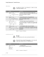
Page 144: ...fied maintenance intervals are guidelines Depending on the quality of the pellets and the power used by the heating system more frequent on off operation the intervals may be extended Interval Component See page After approx 2 5 t pellets as required Empty the ash box Check and clean the stepped grate 146 147 Every 6 months Clean the control unit Inspect and clean the flue pipe Clean the cleaning ...

Page 145: ...ool down slowly Only touch the hot surfaces with the carrying grip or wait until the surfaces have cooled down before starting with the cleaning and maintenance work Caution Danger of fire from hot ash Allow the system to cool down enough to avoid a fire when using a vacuum cleaner Turn the heating system off before carrying out the tasks described below See chapter 6 Using the heating system sect...

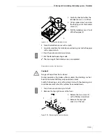
Page 146: ...s from hot surfaces During operation the boiler surfaces under the cladding are hot Even when turned off they only cool down slowly Only touch the hot surfaces with the carrying grip or wait until the surfaces have cooled down before starting with the cleaning and maintenance work 5 Release the ash box fastener To do so press the safety lock 2 to the left and fold the closure 1 inward to open it F...

Page 147: ...r 9 Close the connection piece of the ash box with the cover 3 10 Open the closure 2 11 Empty the ash box 1 into a fireproof container Figure 7 3 Emptying the ash box 2 1 3 Caution Danger of burns from hot surfaces During operation the boiler surfaces under the cladding are hot Even when turned off they only cool down slowly Switch the heating system off and only start with the cleaning and mainte...

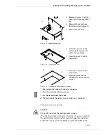
Page 148: ...Removing the deflector plate 2 1 10 Remove the insulating piece 2 11 Remove the two stones 1 lying behind it with the insulation in between 3 Figure 7 6 Removing stones and insulation in between 1 2 3 12 Check the stepped grate 1 for ash and dirt 13 If necessary clean the stepped grate 1 with a vacuum cleaner Figure 7 7 Checking and cleaning the stepped grate 1 ...

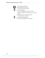
Page 149: ...Set the operating mode to Off 2 Allow the heating system to burn out 3 Turn the mains electricity switch off Figure 7 8 Control unit for HDG Pelletronic Pelletronic Pelletmaster Mode Menu Enter Caution Danger of burns from hot surfaces During operation the boiler surfaces under the cladding are hot Even when turned off they only cool down slowly Switch the heating system off and only start with th...

Page 150: ...switch off Caution Danger of burns from hot surfaces During operation the boiler surfaces under the cladding are hot Even when turned off they only cool down slowly Switch the heating system off and only start with the cleaning and maintenance work when the surfaces have cooled down 3 Releasethetwonuts 1 ofthe cover 2 with a 17 mm spanner 4 Remove the cover 2 Figure 7 10 Opening the cleaning shaft...

Page 151: ... to Off 2 Allow the heating system to burn out 3 Turn the mains electricity switch off 4 Open the left door of the boiler 5 Remove the pressure equalisation hose 2 if connected 6 Pull the ignition fan 1 out of the retainer 3 7 Unscrew the four M4 stainless steel slotted screws 4 of the hot air nozzle 5 8 Pull off the hot air nozzle 5 9 Remove the insulating tube 6 and the seal 3 Figure 7 12 Disass...

Page 152: ... Set the desired operating mode The cleaning of the ignition fan is completed CHECKING AND CLEANING THE LAMBDA SENSOR 1 Set the operating mode to Off 2 Allow the heating system to burn out 3 Turn the mains electricity switch off Caution Danger of burns from hot surfaces During operation the boiler surfaces under the cladding are hot Even when turned off they only cool down slowly Switch the heatin...

Page 153: ... check whether the lambda sensor 1 is still hot 6 Using a pipe wrench unscrew the locking nut of the lambda sensor 1 7 Pull the lambda sensor 1 out of the flue pipe 2 Figure 7 15 Cleaning the lambda sensor 1 2 Caution Danger of burns from hot surfaces During operation the boiler surfaces under the cladding are hot Even when turned off they only cool down slowly Switch the heating system off and on...

Page 154: ...he heating system to burn out 2 Turn the mains electricity switch off 5 Unscrew the flue sensor 2 using a 13 mm spanner 6 Pull the flue sensor 2 out of the flue pipe 1 Figure 7 17 Removing the flue sensor 1 2 Caution Danger of burns from hot surfaces During operation the boiler surfaces under the cladding are hot Even when turned off they only cool down slowly Switch the heating system off and onl...

Page 155: ...er 2 Figure 7 19 Removing the cover 2 1 3 8 Clean the sieve 1 on the underside of the cover 2 with a vacuum cleaner 9 Clean the cover 2 with a moist cloth Figure 7 20 Cleaning the sieve 1 2 10 Clean the sensor 1 with a moist cloth 11 Clean the pellet vacuum container 2 with a vacuum cleaner Figure 7 21 Cleaning the pellet vacuum container 1 2 Caution Danger of injury from the rotating delivery aug...

Page 156: ... mains electricity switch off 3 Open the access door 4 Remove the wooden boards inside the access door 5 Clean the slanted floor and the delivery auger with a vacuum cleaner 6 Close the access door in the reverse sequence 7 Turn the mains electricity switch on 8 Set the desired operating mode The cleaning of the pellet bunker is completed ...

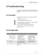
Page 157: ...mbol for the current operating mode lights up The fault message is no longer shown in the display The fault is fixed 8 2 Possible faults Enter No Fault Cause Remedy Mains switch is turned on but the indicator in the switch does not light up Circuit breaker of the mains supply is turned off Mains supply is not connected Microfuse underneath the mains switch is faulty Switch on the circuit breaker o...

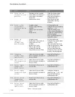
Page 158: ... Par 7 02 Clean or replace the sensor Check the ignition fan stoker auger and temperature sensor in the combustion chamber and have any fault fixed by a heating engineer F010 Combuston chamber temp Open circuit Open circuit in sensor cable Sensor incorrectly connected Sensor is faulty Have the fault fixed by a qualified electrician F011 Open circuit in flue temperature sensor Open circuit in senso...

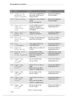
Page 159: ...ffer temperature sensor Short circuit in the sensor or sensor cable Have the fault fixed by a qualified electrician F022 Open circuit in upper buffer temperature sensor Open circuit in sensor cable Sensor incorrectly connected Sensor is faulty Have the fault fixed by a qualified electrician F023 Short circuit in lower buffer temperature sensor Short circuit in the sensor or sensor cable Have the f...

Page 160: ...ied electrician F033 RAM fault Buffer battery Buffer battery on central unit is faulty Have the fault fixed by a qualified electrician F035 Heating circuit module 0 is not connected Power supply has failed Bus cable is not connected Bus cable is incorrectly connected Check the power supply Have the fault fixed by a qualified electrician F040 Supply temp CCT1 open circuit Sensor not connected Senso...

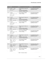
Page 161: ...ble Both sensor connections joined in a single terminal Have the fault fixed by a qualified electrician F050 Indoor thermostat unit CCT3 open circuit Sensor not connected Sensor is faulty Have the fault fixed by a qualified electrician F051 Indoor thermostat unit CCT3 Short circuit Short circuit in sensor or in cable Both sensor connections joined in a single terminal Have the fault fixed by a qua...

Page 162: ...ons joined in a single terminal Have the fault fixed by a qualified electrician F060 Open circuit in temperature sensor for district heating Sensor not connected Sensor is faulty Have the fault fixed by a qualified electrician F061 Short circuit in temperature sensor for district heating Short circuit in sensor or in cable Both sensor connections joined in a single terminal Have the fault fixed by...

Page 163: ... in sensor or in cable Both sensor connections joined in a single terminal Have the fault fixed by a qualified electrician F086 Indoor thermostat unit CCT4 Open circuit Indoor thermostat unit not connected Indoor thermostat unit is faulty Have the fault fixed by a qualified electrician F087 Indoor thermostat unit CCT4 Short circuit Short circuit in indoor thermostat unit Incorrect terminal connect...

Page 164: ...it module 1 ADC fault Analogue to digital converter is faulty New heating circuit control F104 Heating circuit module 1 Fault in 0 throughput Speed controlled output is faulty New heating circuit control F170 No connection to GSM module GSM module can not be signalled by the central unit Cable connection is faulty GSM module without voltage or faulty Have the fault fixed by a qualified electrician...

Page 165: ...ll flash underneath the parameter 0 The value displayed can be changed 4 Press the Plus button The value of the parameter is increased to 1 5 Press the Enter button The changed value is confirmed Emergency operation has been configured 6 Press the Menu button twice The standard display of i 01 is shown FURTHER MEASURES Have the fault fixed by an authorised heating engineer F202 CAN data transmissi...

Page 166: ...ch will extinguish The control is deactivated 4 Switch off the circuit breaker for the heating system 5 Disconnect the heating system from the electrical power supply 6 Once it has cooled down drain the heating water from the system 7 Observe the safety regulations for personnel when disconnecting the boiler from the heating system 8 Dismantle the individual components of the heating system The he...

Page 167: ...breglass mineral wool and plastic parts such as suction hoses etc should be handed in to the respective waste disposal centres The geared motors used consist largely of materials which can be recycled If a geared motor cannot be handed over complete to a suitable company for proper disposal proceed as follows 1 The gear oil must be drained into a suitable container 2 The geared motor should be dis...

Page 168: ...ual The installation of the heating system and the hydraulic components must meet the requirements in the operating manual and the specified HDG hydraulic diagrams The heating system must be installed according to applicable rules regulations and guidelines The pellet quality must correspond to the requirements specified by HDG Bavaria GmbH An HDG delivery system must be used 10 3 Warranty exclusi...

Page 169: ... HDG Bavaria GmbH 08 2008 HDG Pelletmaster 15 25 V 03 en 11 EC Declaration of Conformity 169 11 EC Declaration of Conformity ...

Page 170: ...170 HDG Pelletmaster 15 25 V 03 en HDG Bavaria GmbH 08 2008 ...

Page 171: ......

Page 172: ...aria GmbH Heizsysteme für Holz Siemensstraße 22 D 84323 Massing Tel 49 0 8724 897 0 info hdg bavaria com www hdg bavaria com Art Nr 9980000172 V 03 en 08 2008 Translation of the original operating instructions ...

Reviews: