4 Planning and installation – Electrical system
78
3.
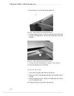
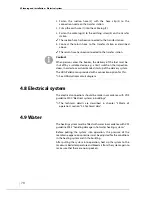
Fasten the suction hose (2) with the hose clip (3) to the
connection nozzle on the transfer station.
4.
Crimp the earth wire (1) into the cable lug (5).
5.
Fasten the cable lug (5) to the earthing screw (4) on the transfer
station.
✓
The suction hose has been connected to the transfer station.
6.
Connect the return hose to the transfer station as described
above.
✓
The return hose has been connected to the transfer station.
4.8 Electrical system
The electrical connections should be made in accordance with VDE
guideline 0100 “Electrical systems in buildings”.
✎
The technical details are described in chapter “3 Mode of
operation”, section “3.3 Technical data”.
4.9 Water
The heating system must be filled with water in accordance with VDI
guideline 2035 “Avoiding damage in hot water heating systems”.
Before putting the system into operation, the pressure of the
membrane expansion container must be adjusted for the conditions
in the heating system and in the building.
After putting the system into operation, heat up the system to the
maximum boiler temperature and bleed air from the system again to
make sure that there are no air pockets.
Caution!
When persons enter the bunker, the delivery of the fuel must be
shut off by a suitable device, e.g. a limit switch on the inspection
doors, in order to avoid unintended start-up of the delivery system.
The HDG Pelletronic is provided with a connection option for this.
✎
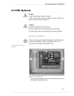
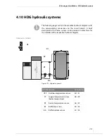
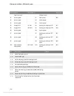
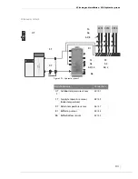
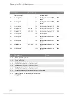
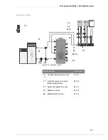
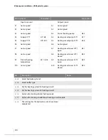
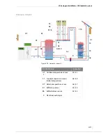
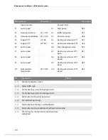
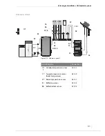
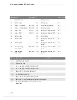
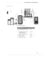
See HDG Hydronic circuit diagram.
Summary of Contents for Pelletmaster 15
Page 1: ...hdg bavaria com HDG Pelletmaster 15 25 Operation Manual V 03 08 2008 ...
Page 2: ......
Page 170: ...170 HDG Pelletmaster 15 25 V 03 en HDG Bavaria GmbH 08 2008 ...
Page 171: ......

