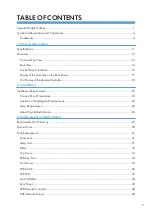
Connecting Component Input.................................................................................................................. 123
Connecting HDMI Input............................................................................................................................124
Connecting to a Wired LAN.....................................................................................................................126
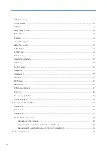
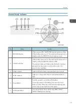
Power Indicator.................................................................................................................................127
Status Indicator................................................................................................................................. 127
Lamp Indicator.................................................................................................................................. 130
Temp. Indicator................................................................................................................................. 130
If the temperature protector is activated......................................................................................... 131
Menus and functions to be added by the Expert Mode................................................................132
Menus and functions to be added by the Service Mode..............................................................134
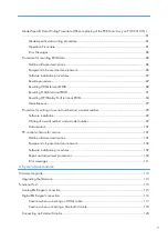
Operation Check for the Main Board..................................................................................................... 138
For Video....................................................................................................................................................139
For Audio................................................................................................................................................... 140
For Multi Media.........................................................................................................................................141
Operation Check for the PCB Network...................................................................................................141
Displaying the error log screen....................................................................................................... 142
Service Information: Page-1............................................................................................................ 142
Service Information: Page-2............................................................................................................ 143
Service Information: Page-3............................................................................................................ 144
Service Information: Reset................................................................................................................144
8
Summary of Contents for Sirius-PJ2
Page 1: ...Model Sirius PJ2 Machine Codes Y076 Y077 Y078 Field Service Manual June 2015 ...
Page 2: ......
Page 12: ...10 ...
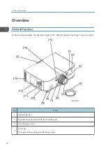
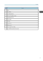
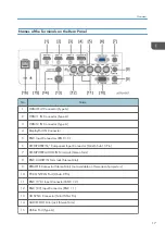
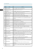
Page 20: ...No Name 16 Ethernet Port RJ 45 Part Names of the Remote Controller 1 Product Information 18 ...
Page 24: ...1 Product Information 22 ...
Page 34: ...Filters 1 Remove the Filter cover A 2 Remove the Filters A 3 Replacement and Adjustment 32 ...
Page 36: ...5 Disconnect the cable 1 PCB Key Pad 1 Top cover page 33 3 Replacement and Adjustment 34 ...
Page 54: ...5 Remove the Duct Cover A 3 6 Remove the Duct Base A 3 3 Replacement and Adjustment 52 ...
Page 67: ...3 Remove the bracket A 2 4 Remove the Power supply DC 6 Parts Replacement 65 ...
Page 153: ...MEMO 151 ...
Page 154: ...MEMO 152 EN ...
Page 155: ...Model Sirius PJ2 Machine Codes Y076 Y077 Y078 Appendices June 2015 ...
Page 156: ......
Page 158: ...2 ...
Page 172: ...MEMO 16 EN ...


