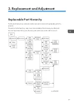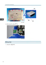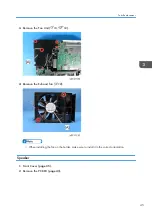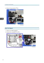
2.
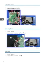
Remove the USB Network Board ( ×1,
×1)
PCB Main Ass'y
• Replacing the PCB Main Ass'y involves making adjustments to the software (refer to Electrical
Adjustment). Before removing the Ass'y, be sure to read (or copy) all data.
1.
2.
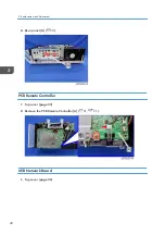
Remove the PCB Remote Controller (
3.
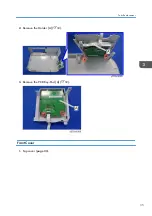
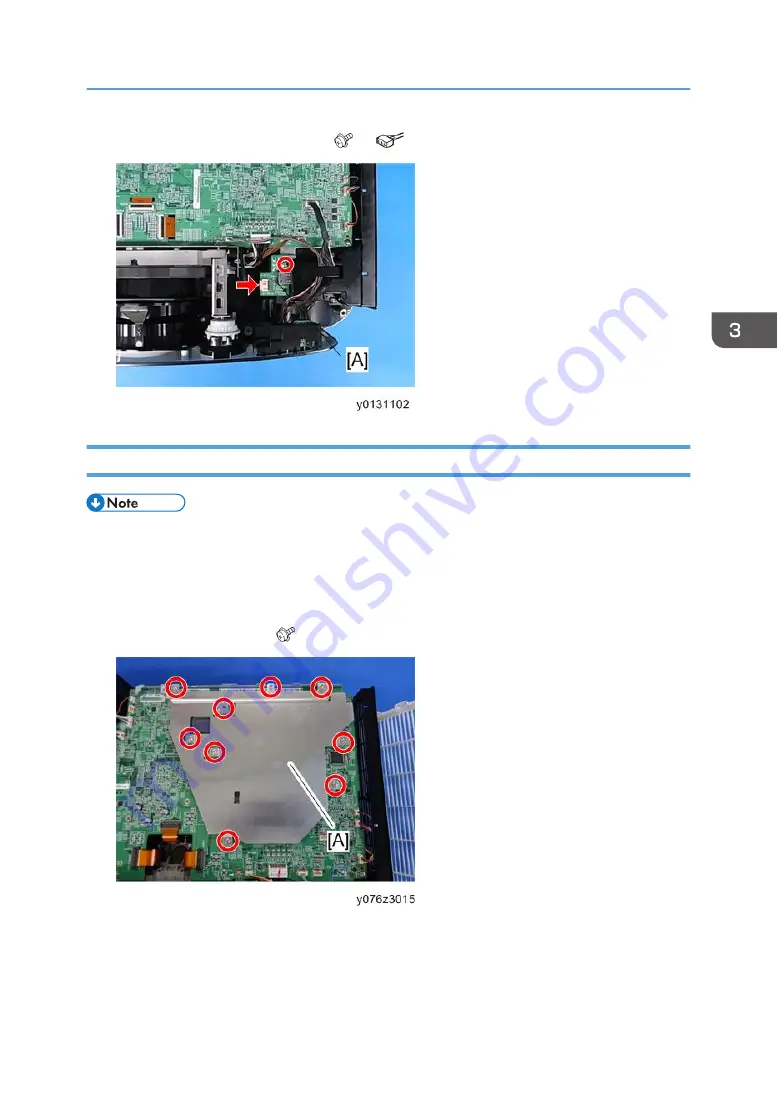
Remove the bracket [A] ( ×9).
Parts Replacement
41
Summary of Contents for Sirius-PJ2
Page 1: ...Model Sirius PJ2 Machine Codes Y076 Y077 Y078 Field Service Manual June 2015 ...
Page 2: ......
Page 12: ...10 ...
Page 20: ...No Name 16 Ethernet Port RJ 45 Part Names of the Remote Controller 1 Product Information 18 ...
Page 24: ...1 Product Information 22 ...
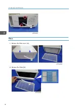
Page 34: ...Filters 1 Remove the Filter cover A 2 Remove the Filters A 3 Replacement and Adjustment 32 ...
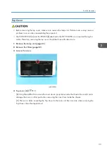
Page 36: ...5 Disconnect the cable 1 PCB Key Pad 1 Top cover page 33 3 Replacement and Adjustment 34 ...
Page 54: ...5 Remove the Duct Cover A 3 6 Remove the Duct Base A 3 3 Replacement and Adjustment 52 ...
Page 67: ...3 Remove the bracket A 2 4 Remove the Power supply DC 6 Parts Replacement 65 ...
Page 153: ...MEMO 151 ...
Page 154: ...MEMO 152 EN ...
Page 155: ...Model Sirius PJ2 Machine Codes Y076 Y077 Y078 Appendices June 2015 ...
Page 156: ......
Page 158: ...2 ...
Page 172: ...MEMO 16 EN ...

