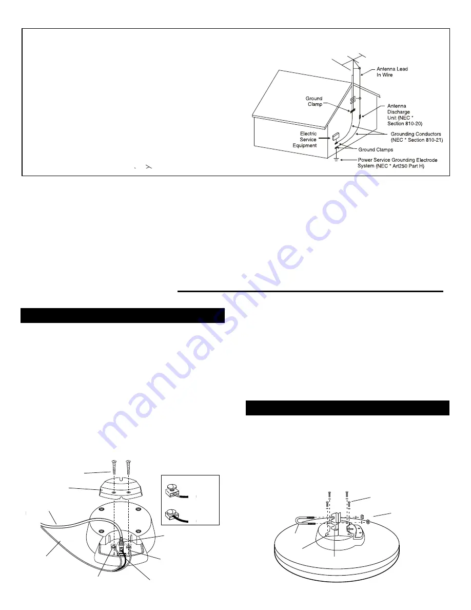
1. Loosen the two screws on the terminal board cover on the
bottom of the antenna. This will expose a threaded coaxial
receptacle and three special screw-type terminals.
2. Screw the supplied coaxial cable’s lead-in connector onto the
threaded terminal.
Caution:
Be sure the center conductor of
the cable is in the hole of the F-connector before tightening.
3. Your antenna may have either Yellow/Black/White wires
or Red/Black/Blue rotator wires.
Note:
Only loosen clamping terminals up to two turns, as
backing them out further can cause the screws to become
unattached from their internal mounts.
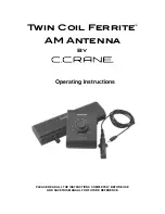
1. Attach the antenna mounting bracket to the four slotted
metal inserts on the bottom of the antenna using the four
screws and lockwashers provided.
(
Do not unscrew recessed
metal inserts. They hold the internal motor in place.)
2. Insert the U-bolt into the mounting bracket using the two
washers and hex nuts. Do not tighten.
EXAMPLE OF ANTENNA GROUNDING ACCORDING TO
NATIONAL ELECTRICAL CODE INSTRUCTIONS CONTAINED
IN ARTICLE 810-”RADIO AND TELEVISION EQUIPMENT”
a
Use No. 10 AWG (5.3 mm
2
) copper, No. 8 AWG (8.4 mm
2
) aluminum, No. 17
AWG (1.0 mm
2
) copperclad steel or bronze wire, or larger, as a ground wire.
b
Secure antenna lead-in and ground wires to house with stand-off insula-
tors spaced from 4-6 feet (1.22-1.83 m) apart.
c
Mount antenna discharge unit as close as possible to where lead-in
enters house.
d
Use jumper wire not smaller than No. 6 AWG (13.3 mm
2
) copper, or the
equivalent, when a separate antenna-grounding electrode is used. See
NEC Section 810-21 (j).
a
Use
No. 10
AWG
(5.3 mm
2
) copper
, No.
8 AWG
(8.4 mm
2
)
aluminum,
N
o. 17
A
WG (1.0 mm
2
) copperclad steel or bronze wire, or larger, as a ground wire.
b
Secure antenna lead-in and ground wires
to
house with stand-of
f
insula
-
tors spaced from 4-6 feet (1.22-1.83 m) apart.
c
Mount antenna discharge unit as
close
as possible
to
where lead-in
enters house.
d
Any grounding electrode added
for
communications systems
is
required
to
be bonded with a No. 6
AWG
(13.3 mm
2
) or
larger conductor
to the
building
or
structure grounding electrode system in accordance with
NEC
800.40(D), 810.21(J), 820.40(D) and 830.40(D).
Included in the HDView360 Mini-State Antenna
• HDTV/VHF/UHF antenna with amplifier and internal
rotator
• RF remote and receiver
• 12VDC adapter with fused powercord
• 60' combination coaxial/3-wire rotator cable
• Stainless steel mounting hardware kit
• 12VDC power adapter
Specifications:
Bandpass VHF ................................... 54-88, 174-216 MHz
Bandpass UHF ...............................................470-806 MHz
FM trap (fixed) ...........................88-108 MHz, 20 dB typical
VHF/UHF Gain ...................................................up to 20dB
Impedance ....................................... 75 Ohms, Unbalanced
Power Requirement ......................12VDC, 120 VAC, 60 Hz
Weatherproof housing .............UV-protected, filled copolymer
Mounting .................................. 1½ inch
(maximum)
round mast
Specifications are typical: Individual units may vary. Specifications are
subject to change and improvement without notice.
Fasten the Yellow or Red rotator control wire to terminal
1, the Black wire to terminal 2, and the White or Blue wire
to terminal 3. Insert the wire between the upper and lower
clamps of the terminal body. Tighten the screw as shown.
4. Replace the terminal cover so that the coaxial cable comes
out through the notch. Tighten the terminal cover screws.
This will clamp the rotator cable in place.
Terminal Board
Cover
Coaxial Cable
3-Wire
Rotator Cable
1
Yellow or Red Wire
2
Black Wire
3
White or Blue Wire
Threaded Coax
Receptacle
Terminal Board
Cover Screws
Loosened
Terminal Screw
Tightened
Terminal Screw
1
2
3
3
Mounting
Bracket
Metal
Inserts
U-Bolt
Screws and Lockwashers
Washers and
Hex Nuts
Connecting Cable to the Antenna
Installation of your Antenna
Attaching the Mounting Bracket


