9 HOMEDEPOT.com
Please contact 1-800-514-6729 for further assistance.
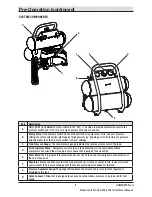
Part
Description
A
ON ( I )/OFF ( 0 ) Switch:
Turn this switch in the “ON ( I )” position to provide automatic power to the
pressure switch and “OFF ( O )” to remove power at the end of each use.
B
Safety Valve:
If the pressure switch does not shut off the air compressor at its “cut-out” pressure
setting, the safety valve will protect against high pressure by “popping out” at its factory set pressure
(slightly higher than the pressure switch “cut-out” setting).
C
Tank Pressure Gauge:
The tank pressure gauge indicates the reserve air pressure in the tank.
D
Air Compressor Pump:
Compresses air into the air tank. Working air is not available until the
compressor has raised the air tank pressure above that required at the air outlet.
E
Drain Valve
: The drain valve is located at the base of the air tank and is used to drain condensation at
the end of each use.
F
Regulator:
Valve used to ensure that the tank pressure never reaches unsafe levels. It also allows the
user to adjust the pressure coming out of the tank to match what is needed for the task.
G
Pressure Regulator Gauge:
The gauge that indicates the amount of pressure that the regulator is
providing to the tool.
H
Quick Connect:
Fitting that is designed to accept a hose that allows pressure to be released for tool
usage.
SYSTEM COMPONENTS
Pre-Operation (continued)
A
D
B
E
C
F
G
H


