15
Assembly Instruction
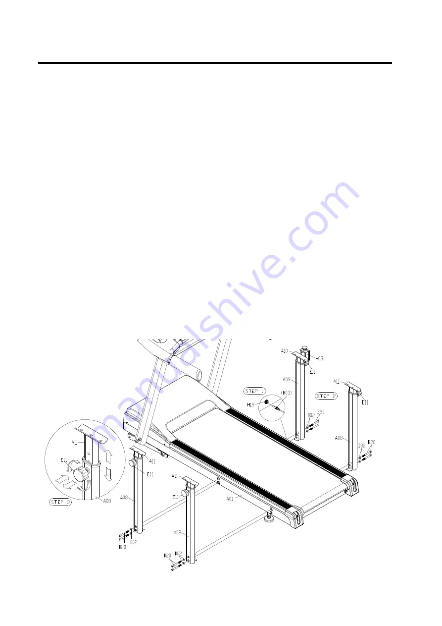
Step 9
:
Part 1:
Connect the connector which is from the Emergency Switch (H03) to the Emergency Switch
Jack (H19) wire which is out from the Control Board ( High Speed) (H17) as the diagram.
Part 2:
Install the Side Support Posts (Long&Short)(A08&A09) to two sides of the Main Frame(A01)
respectively as the diagram , per the following parts .
Qty 8
–
(B20)
M10 x90 L Hex Socket Cap Screw (Sliver)
Qty 8
–
(D02)
Ø10.2 x Ø20 x 2.0T Washer
Part 3:
a. Turn Adjustment Knob (E11) counterclockwise to loosen.
b. Pull Adjustment Knob (E11) out and adjust to your desired position as diagram
c. Re-secure the Adjustment Knob (E11) and turn clockwise until tight to remove any
looseness.
* IMPORTANT
Adjustment Knob ( E11) must be locked tightly into the holes of Side Support Post (Long & Short)
(A08&A09) as the diagram before your exercising on the machine
.


