The Cleaning Spray Gun features a new type of
internal flow control
mechanism. It permits the
smooth and simple adjust-
ment of the water or air
flow across the entire
range of the trigger move-
ment. If required, the
maximum water or air
pressure value can be set
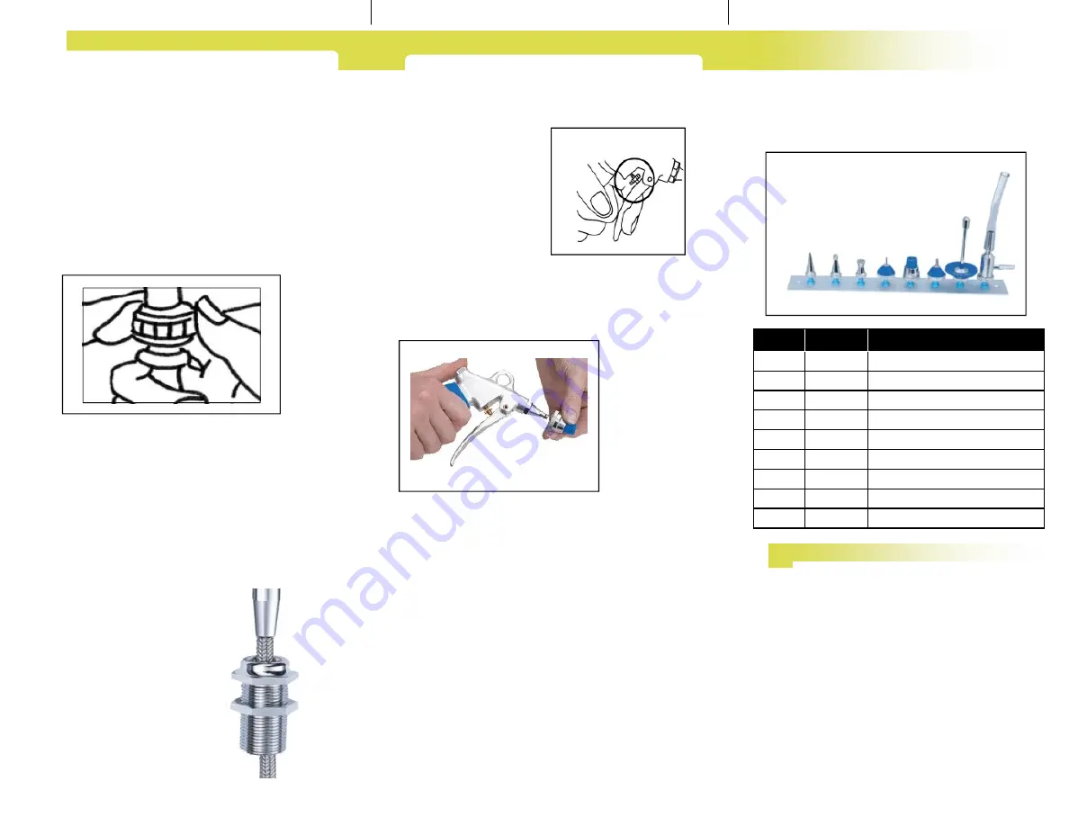
by using the small threaded
nut (Fig. 2) located behind the trigger handle.
The flow is determined by pulling up to the set
maximum point threaded. Prior to operation, the
user must
make sure that
the attach-
ments are cor-
rectly seated
on the safety
conell by sim-
ply pushing
them onto the
spray gun rin-
ser tip (Fig.3 &
3A). Even high pressure cannot disconnect them.
When in operation, the Spray Gun must not be
pointed at parts or orifices of the body because the
compressed water or air jet may be harmful. De-
pending on the field of application, suitable safety
measures must be taken to protect the user from
splashes of contaminated water (protective goggles,
protective mask, etc.). If other tubings than those
supplied by Healthmark are to be used, it must be
ensured that they have been approved by a testing
lab. Warranty claims will only be honored for com-
ponents purchased from Healthmark.
Specifications:
max. water or air pressure 6 bar (86
psi)
Safety Instructions:
The Spray Gun is not a medi-
cal product and is therefore not to be used as part of
medical treatments.
I N S T R U C T I O N O F U S E
The Spray Gun with the blue silicone grip may
only be cleaned with warm water and a mild de-
tergent. It is not necessary to carry out water qual-
ity tests, but the user should not operate the Spray
Gun with de-mineralized water since it causes
corrosion. It is recommended to decalcify the
Spray Gun approximately every four weeks. The
gun should be disassembled and the inner parts
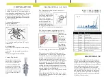
(Fig. 5 #8 (80-00-44) ) placed in a decalcifying
agent. This is beneficial for the service life and
reliability of the spray gun.
M A I N T E N A N C E
Fig. 2
Fig. 3
No.
Part No.
Description
1
80-01-05
Universal tip
2
80-01-06
For drainage tube
3
80-01-08
Spray jet for rinsing out glassware, etc.
4
80-10-40
For syringes and cannulae with cone
5
80-10-41
For pipettes
6
80-10-42
For syringes and cannulae with Luer cone
7
80-10-43
For bottles and Erlenmeyer flasks
8
80-10-44
Water jet for suction pump cannisters
1-8
80-01-38
Complete set with rack
P I C K T H E C O R R E C T
T I P A T T A C H M E N T S
Congratulations on the purchase of your new
Cleaning Spray Gun! You are moments away
from using this outstanding new tool. It is easy
to install for either water or air. It is best in-
stalled by a licensed plumber. Please contact
Facilities and/or Engineering concerning any
special requirements.
Connection Requirements:
Water Connection:
Plumbing threaded tap or valve - 3/8”, 1/2” or
3/4” (standard gun kit includes 3/4” female
connection).
Air Connection:
If operated with compressed air, the tubing
must be
connected to the air supply by suitable con-
nector
(cannot be supplied by Healthmark).
Counter Top Rosette
If you plan to connect your
gun to water or air below the
counter we recommend a
rosette be installed. It will
minimize potential friction
damage to the hose. A 1 3/8”
diameter hole will need to be
drilled in the counter or sink
top to accommodate the ro-
sette.
I N S T A L L A T I O N
Fig. 1
Fig. 3A
1
2
3
4
5
6
7
8
1


