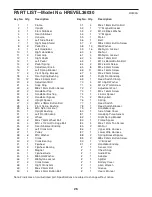
background image

26

Note: # indicates a non-illustrated part. Specifications are subject to change without notice.

1

1

Frame

2

1

Upright

3

1

Front Stabiliser

4

1

Rear Stabiliser

5

1

Console

6

1

Left Side Shield

7

1

Right Side Shield

8

2

Pedal Disc

9

1

Left Handlebar

10

1

Right Handlebar

11

2

Foam Grip

12

1

Right Pedal

13

1

Left Pedal

14

2

Pedal Spring

15

2

Adjustment Knob

16

1

Left Spring Bracket

17

2

Front Spring Bracket

18

4

Rear Spring Bushing

19

12

M6 x 33.5mm Bolt

20

2

Adjustment Bolt

21

4

Snap Ring

22

2

M8 x 19mm Button Screw

23

2

Handlebar Cap

24

4

Handlebar Bushing

25

2

Handlebar Spacer

26

2

Upright Spacer

27

2

M10 x 78mm Button Bolt

28

4

Front Spring Bushing

29

6

M10 Nylon Locknut

30

1

Upright Bushing

31

1

Left Front Endcap

32

2

Wheel

33

2

M6 x 72mm Wheel Bolt

34

4

M10 x 112mm Carriage Bolt

35

2

Rear Stabiliser Endcap

36

1

Left Crank Arm

37

1

Pulley

38

6

M10 Washer

39

1

Crank

40

2

Crank Bearing

41

1

Flywheel

42

2

Flywheel Bearing

43

1

Magnet

44

1

Flywheel Axle

45

3

M8.5mm Washer

46

7

M8 Nylon Locknut

47

2

Crank Screw

48

1

Right Crank Arm

49

1

M6 x 25mm Bolt

50

4

M8 x 45mm Button Bolt

51

4

M6 x 18mm Button Bolt

52

1

“C” Magnet Bracket

53

2

M10.3 Black Washer

54

1

“C” Magnet

55

1

Motor

56

1

Belt

57

2

M8 x 33mm Button Screw

58

13

M6 Washer

59

16

M6 Nylon Locknut

60

4

M6 Nut

61

4

M5 Nylon Locknut

62

4

M5 x 12mm Bolt

63

1

M10 x 88mm Button Bolt

64

2

M4 x 6mm Screw

65

8

M5 x 33mm Screw

66

11

M4 x 16mm Screw

67

4

M4 x 25mm Screw

68

1

Right Front Endcap

69

1

Reed Switch Clamp

70

4

M10 Split Washer

71

3

M10 x 27mm Screw

72

2

Adjustment Foot

73

1

M5 x 16mm Screw

74

1

4.5mm Spacer

75

2

M6 Eyebolt

76

1

Spring

77

1

Reed Switch

78

1

Reed Switch Bracket

79

2

Handlebar Leg

80

1

Side Shield Cover

81

1

Handgrip Pulse Sensor

82

1

Right Spring Bracket

83

1

Frame Spacer

84

4

M4 x 12mm Tap Screw

85

2

M5 Nut

86

1

Upper Wire Harness

87

1

Lower Wire Harness

88

2

Spring Bracket Spacer

89

2

M8 x 22mm Button Screw

90

1

“U” Bracket

91

2

Handlebar Endcap

#

1

Sensor Unit

#

1

Chest Strap

#

1

Audio Wire

#

1

Adapter

#

1

Splitter

#

1

Battery Cover

#

1

Allen Wrench

#

1

Grease

#

1

Userʼs Manual

Key No. Qty.

Description

Key No. Qty.

Description

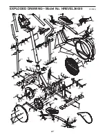
PART LIST—Model No. HREVEL36030

R0903A

Summary of Contents for Cross Trainer 990S

Page 1: ...Visit our website at USER S MANUAL QUESTIONS As a manufacturer we are com mitted to providing complete customer satisfaction If you have questions or if there are missing or damaged parts please call...

Page 2: ...be used by persons weighing more than 115 kg 250 lbs 7 Wear appropriate exercise clothes when using the elliptical crosstrainer Always wear athletic shoes for foot protection 8 Always hold the handgr...

Page 3: ...manual carefully before you use the elliptical crosstrainer If you have ques tions after reading this manual please call our Customer Service Department at 08457 089 009 To help us assist you please...

Page 4: ...ly The number in parenthesis below each drawing refers to the key number of the part from the PART LIST on page 26 The second number refers to the quantity used in assembly Note Some small parts may h...

Page 5: ...per Wire Harness insert the Upright into the Frame 1 Do not pinch the Wire Harnesses Slide an M10 Split Washer 70 and a Frame Spacer 83 onto the M10 x 88mm Button Bolt 63 and insert the Button Bolt in...

Page 6: ...the excess wire harness into the Upright 2 Next attach the Console to the Upright with three M10 x 27mm Screws 71 and three M10 Split Washers 70 Be careful to avoid pinching the wire harnesses Snap t...

Page 7: ...tify the Left Pedal 13 Attach the Left Pedal to the left Pedal Spring 14 with an Adjustment Bolt 20 an M10 Washer 38 and an Adjustment Knob 15 as shown Note The Left Pedal can be attached in several p...

Page 8: ...sensor does not function when positioned as described move it slightly lower or higher on your chest Each time you use the chest pulse sensor use saline solution such as saliva or contact lens solu t...

Page 9: ...are wetted and the chest pulse sen sor is put on the chest pulse sensor shuts off when it is removed and the electrode areas are dried If the chest pulse sensor is not dried after each use it may rema...

Page 10: ...elliptical crosstrainer wait until the pedals come to a complete stop Note The elliptical crosstrainer does not have a free wheel the ped als will continue to move until the flywheel stops When the p...

Page 11: ...e watts program changes the pedalling resistance and prompts you to vary your pace to keep your power output near a target level The console also features iFIT com interactive technol ogy Having iFIT...

Page 12: ...s MPH or Km H will appear when your heart rate is shown the letters BPM will appear G Pace indicators When the manual mode is select ed only the left pace indicator will appear This indicator will sho...

Page 13: ...can select a single feedback mode for continuous display Press the Display Mode button repeatedly until only the MPH or Km H Time Resist Cals Miles or Kms or Watts indicator appears in the display Ma...

Page 14: ...sis tance setting is programmed for the next period The target pace settings for the program will be shown by the right pace indica tor in the display The left indicator will show your actual pedallin...

Page 15: ...the program However you should hold the handgrips frequently for the program to operate properly Each time you hold the handgrips keep your hands on the metal contacts for at least 30 seconds Note Whe...

Page 16: ...level that you set Follow the steps below to use the watts program Turn on the console See step 1 on page 13 Select the watts program Each time the console is turned on the manual mode will be select...

Page 17: ...the feedback modes See step 4 on page 13 Measure your heart rate if desired See step 5 on page 13 When you are finished exercising the console will automatically turn off See step 6 on page 13 To use...

Page 18: ...phones into the other side of the splitter HOW TO CONNECT YOUR HOME STEREO Note If your stereo has an unused LINE OUT jack see instruction A below If the LINE OUT jack is being used see instruction B...

Page 19: ...ee instruction B If your VCR is connected to your home stereo see HOW TO CONNECT YOUR HOME STEREO on page 18 A Plug one end of the audio cable into the jack beneath the console Plug the other end of t...

Page 20: ...Press the play button on your CD player or VCR A moment after the play button is pressed your personal trainer will begin guiding you through your workout Simply follow your personal trainer s instruc...

Page 21: ...ght corner of the display Go to your computer and start an internet connection Start your Web browser if necessary and go to our Web site at www iFIT com Follow the desired links on our Web site to se...

Page 22: ...On Reset button for about six seconds When the informa tion mode is select ed an E for English miles or an M for metric kilometres will appear in the dis play To change the unit of measure ment press...

Page 23: ...or both of the level ling feet under the front stabiliser until the rocking motion is eliminated HANDGRIP PULSE SENSOR TROUBLESHOOTING Avoid moving your hands whilst using the handgrip pulse sensor Ex...

Page 24: ...to strengthen your cardiovascular sys tem your exercise must be aerobic Aerobic exer cise is activity that requires large amounts of oxygen for prolonged periods of time This increases the demand on...

Page 25: ...lles Stretch With one leg in front of the other reach forward and place your hands against a wall Keep your back leg straight and your back foot flat on the floor Bend your front leg lean forward and...

Page 26: ...mm Washer 46 7 M8 Nylon Locknut 47 2 Crank Screw 48 1 Right Crank Arm 49 1 M6 x 25mm Bolt 50 4 M8 x 45mm Button Bolt 51 4 M6 x 18mm Button Bolt 52 1 C Magnet Bracket 53 2 M10 3 Black Washer 54 1 C Mag...

Page 27: ...8 28 29 27 28 29 30 31 68 32 32 33 34 35 35 34 29 29 29 29 48 36 37 21 39 40 40 21 41 42 42 43 44 46 45 47 47 46 54 55 56 57 57 45 45 61 61 62 63 64 64 65 65 65 66 67 66 85 38 38 38 38 70 66 67 90 78...

Page 28: ...Department Unit 4 Revie Road Industrial Estate Revie Road Beeston Leeds LS118JG UK Tel Outside the UK 0 044 113 387 7133 Fax 0 044 113 387 7125 To help us assist you please be prepared to give the fol...

Reviews: