background image

15

HOW TO USE A PRESET PROGRAM

Preset programs 3 and 4 automatically change the

resistance of the pedals and prompt you to increase

or decrease your pedaling pace as they guide you

through effective workouts. The profiles printed on the

left side of the display show how the resistance level

and the target pace will change during the preset pro-

grams.

Follow the steps below to use a preset program.

1. Turn on the console.

See step 1 on page 12.

2. Select a preset program.

To select preset program 3 or 4, press the

Program/Manual button repeatedly until the num-

ber 3 or 4 appears along the left side of the dis-

play. When a preset program is selected, the dis-

play will show how long the program will last.

3. Begin pedaling to start the program.

Each preset pro-

gram consists of

several time peri-

ods of different

lengths. One resis-

tance level and one

target pace are

programmed for

each period.

At the end of each period of the program, the

resistance level will flash in the display for a few

seconds. The resistance of the pedals will then

automatically change to the resistance level that is

programmed for the next period. Note: If the resis-

tance level is too high or too low, you can override

it by pressing the Increase and Decrease buttons.

However, when the current period ends, the resis-

tance level will automatically change if a different

resistance level is programmed for the next period.

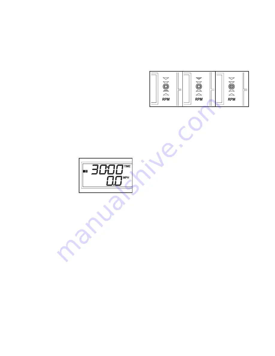
During the program, the pace guide will prompt

you to increase or decrease your pedaling pace.

When one of the two lower indicators lights,

increase your pace; when one of the two upper

indicators lights, decrease your pace. When the

center indicator lights, maintain your current pace.

Important: The pace guide is intended only to

provide a goal. Make sure to pedal at a pace

that is comfortable for you.

The display will show the time remaining in the

program. If you stop pedaling for a few seconds,

the program will pause and the time will flash in

the display. To restart the program, simply resume

pedaling.

4. Monitor your progress with the display.

See step 4 on page 12.

5. Measure your heart rate if desired.

See step 5 on page 12.

6. Turn on the fan if desired.

See step 6 on page 13.

7. When you are finished exercising, the console

will automatically turn off.

See step 7 on page 13.

Summary of Contents for HRCCEX71408.0

Page 1: ...ial number in the space above for reference www healthrider com Visit our website at QUESTIONS As a manufacturer we are com mitted to providing complete customer satisfaction If you have questions or...

Page 2: ...G 19 ORDERING REPLACEMENT PARTS Back Cover LIMITED WARRANTY Back Cover HealthRider is a registered trademark of ICON IP Inc WARNING DECAL PLACEMENT This drawing shows the location s of the warning dec...

Page 3: ...lse sensor is not a medical device Various factors including the user s move ment may affect the accuracy of heart rate readings The pulse sensor is intended only as an exercise aid in determining hea...

Page 4: ...fit read this manual carefully before you use the exercise cycle If you have questions after reading this manual please see the front cover of this manual To help us assist you note the product model...

Page 5: ...assembly Note Some small parts may have been preassembled If a part is not in the parts bag check to see if it has been preassembled M8 Locknut 10 6 M8 Split Washer 41 10 M10 Locknut 33 4 M4 x 16mm S...

Page 6: ...the Upright 13 in the position shown connect the Upper Wire Harness 36 to the Lower Wire Harness 55 Carefully pull the excess Upper Wire Harness 36 out of the top of the Upright 13 and slide the Upri...

Page 7: ...own Make sure that the batteries are oriented as shown by the markings on the battery door Then reattach the battery door 16 Batteries Batteries Door 6 Hold the Console 16 near the Upright 13 Connect...

Page 8: ...adjustment holes in the Seat Post 5 with the indicated hole in the Seat Frame 28 Insert the Seat Knob 11 into the Seat Frame and the Seat Post and turn the Seat Knob clockwise until it is tight Make s...

Page 9: ...e Left Pedal counterclockwise into the left arm of the Crank 21 Tighten the Right Pedal not shown clockwise into the right arm of the Crank Important Tighten both Pedals as firmly as possible After us...

Page 10: ...e Insert the seat knob into the seat frame and the seat post and turn the knob clock wise until it is tight Make sure that the seat knob is inserted into one of the adjustment holes in the seat post H...

Page 11: ...n a steady pedaling pace to keep your heart rate near a target heart rate setting while you exercise The console also offers two preset programs Each program automatically changes the resistance of th...

Page 12: ...g in the program instead of the elapsed time Note The console can display speed and dis tance in either miles or kilometers The letters MPH or KM H will appear in the lower half of the display to show...

Page 13: ...2 Select a pulse program To select pulse pro gram 1 or 2 press the Program Manual button repeatedly until the number 1 or 2 appears along the left side of the display 3 Enter a target heart rate If pu...

Page 14: ...hen the console compares your heart rate to the target heart rate setting the resistance may automatical ly change After the first minute of the program the pace guide will help you to maintain a stea...

Page 15: ...then automatically change to the resistance level that is programmed for the next period Note If the resis tance level is too high or too low you can override it by pressing the Increase and Decrease...

Page 16: ...ved Turn the Crank 21 to the position shown Using an adjustable wrench turn the Left Pedal 24 clockwise and remove it Next remove the indicated M4 x 25mm Screws 42 and the indicated M4 x 16mm Screws 4...

Page 17: ...robic Exercise If your goal is to strengthen your cardiovascular system you must perform aerobic exercise which is activity that requires large amounts of oxygen for prolonged periods of time For aero...

Page 18: ...knut 34 4 M5 Washer 35 2 Levelling Foot 36 1 Upper Wire Harness 37 1 Flywheel 38 1 Magnet 39 1 Right Pedal Strap 40 1 C magnet 41 10 M8 Split Washer 42 4 M4 x 25mm Screw 43 1 Reed Switch Wire 44 1 Cra...

Page 19: ...37 40 43 44 6 48 19 30 30 33 33 33 49 41 42 49 49 34 45 45 45 41 41 41 27 38 21 55 53 7 49 49 42 41 10 47 34 28 9 20 11 56 56 52 52 56 54 41 45 45 41 45 41 23 23 14 31 47 35 35 50 32 10 42 49 42 46 2...

Page 20: ...damage abuse misuse improp er or abnormal usage or repairs not provided by an ICON authorized service center products used for commercial or rental purposes or products used as store display models No...

Reviews: