background image

Hearth & Home Technologies  •  BE-32  •  InD  •  2099-985  Rev. C  •  9/06

47

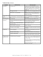
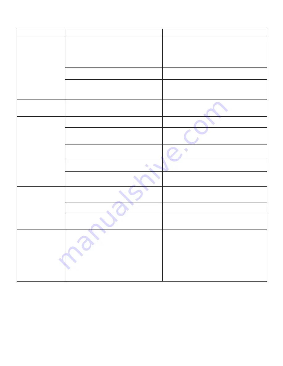
Troubleshooting (continued)

Symptom

Possible Cause

Corrective Action

3. Continued

c. Defective valve.

Turn the valve knob to the ON position. Place the 
ON/OFF switch in the ON position. Check the millivolt 
meter a the thermopile terminals. The millivolt meter 
should read greater than 125mV. If the reading is ac-
ceptable, and if the burner does not come on, replace 
the gas valve.

d. Plugged burner orifi ce.

Check the burner orifi ce for stoppage. Remove stop-
page.

e. Wall switch or wires are defective.

Follow the corrective action in Symptom and Pos-
sible Cause 1.a above. Check the switch and wiring. 
Replace where defective.

4. Frequent pilot outage 
problem.

a. Pilot fl ame may be too high or too low, or blow-
ing out (high pressure), causing pilot safety to drop 
out.

Clean thermocouple and adjust the pilot fl ame for 
maximum fl ame impingement. Follow lighting instruc-
tions carefully.

5. The pilot and main 
burner extinguish while 
in operation.

a.  No LP in tank.

Check the LP (propane) tank. Refi ll the fuel tank.

b.  Inner vent pipe leaking exhaust gases back into 
the system.

Check venting system for damage. Replace/repair 
improperly assembled pipe sections.

c. Glass too loose and air tight packet leaks in 
corners after usage.

Replace glass panel assembly.

d. Bad thermopile or thermocouple.

Replace if necessary.

e. Improper vent cap installation.

Check for proper installation and freedom from debris 
or blockage.

6. Glass soots.

a. Flame impingement.

Adjust the log set so that the fl ame does not exces-
sively impinge on it.

b. Improper air shutter setting.

Adjust the air shutter located on the control panel.

c. Debris around air shutter.

Inspect the opening at the base of the burner. NO MA-
TERIAL SHOULD BE PLACED IN THIS OPENING.

7.  Flame burns blue 
and lifts off burner.

a. Insuffi cient oxygen being supplied.

Ensure that the vent cap is installed properly and free 
of debris. Ensure that the vent system joints are tight 
and have no leaks.

Ensure that no debris has been placed at the base of, 
or in the area of the air holes in the center of the base 
pan beneath the burner.

Ensure that the glass is tightened properly on the unit, 
particularly on top corners.

Summary of Contents for BE-32

Page 1: ...n same room as appliance Alert children and adults to hazards of high temperatures Do NOT operate with protective barriers open or removed Keep clothing furniture draperies and other combustibles away Glass and other surfaces are hot during operation and cool down Keep children away DO NOT DISCARD THIS MANUAL CAUTION This appliance may be installed as an OEM installation in manufactured home USA o...

Page 2: ...ant to read and carefully follow all of the instructions contained in this Owner s Manual Pay special attention to all Cautions and Warnings This Owner s Manual should be retained for future reference We suggest that you keep it with your other important documents and product manuals The information contained in this Owner s Manual unless noted otherwise applies to all models and gas control syste...

Page 3: ...23 B Rear Vent 24 C Securing and Leveling the Appliance 25 Section 8 Installing Vent Pipe A Assembly of Vent Sections for DVP Pipes 26 B Disassembly of Vent Sections 28 C Installing Heat Shield and Horizontal Termination Cap 30 D Installing Roof Flashing and Vertical Termination Cap 32 Î Î Î Section 9 Gas Information A Fuel Conversions 34 B Gas Pressures 34 C Gas Connection 34 Section 10 Electrica...

Page 4: ...ng by changing the existing burner orifice to a smaller size Input rate should be reduced by 4 for each 1000 feet above a 2000 foot elevation in the U S A or 10 for elevations between 2000 and 4500 feet in Canada If the heating value of the gas has been reduced these rules do not apply To identify the proper orifice size check with the local gas utility If installing this appliance at an elevation...

Page 5: ... in print size no less than one half 1 2 inch in size GAS VENT DIRECTLY BELOW KEEP CLEAR OF ALL OBSTRUCTIONS Inspection The state or local gas inspector of the side wall horizontally vented gas fueled equipment shall not approve the installation unless upon inspection the inspector observes carbon monoxide detectors and signage installed in accordance with the provisions of 248 CMR 5 08 2 a 1 thro...

Page 6: ...rom the packaging The vent system components and trim doors are shipped in separate packages The gas logs may be packaged separately and must be field installed Report to your dealer any parts damaged in shipment particularly the condition of the glass Read all of the instructions before starting the in stallation Follow these instructions carefully dur ing the installation to ensure maximum safet...

Page 7: ...ss Locate appliance away from traffic areas A Selecting Appliance Location When selecting a location for your appliance it is important to consider the required clearances to walls see Figure 3 1 Figure 3 1 Appliance Locations NOTE For actual appliance dimensions refer to Sec tion 16 In addition to these framing dimensions also reference the following sections Clearances and Mantel Projections Sec...

Page 8: ...ons where cold air infiltration may be an issue the inside surfaces may be sheetrocked and taped for maximum air tightness To further prevent drafts the wall shield and ceiling firestops should be caulked with high temperature caulk to seal gaps Gas line holes and other openings should be caulked with C Clearances Figure 3 2 Clearances to Combustibles Fire Risk Odor Risk Install appliance on hard ...

Page 9: ... C 9 06 9 D Mantel Projections Figure 3 3 Clearances to Mantels or other Combustibles above Appliance Figure 3 4 Clearances to Mantel Legs or Wall Projections Acceptable on both sides of opening 1 2 Note Clearance from opening to perpendicular wall ...

Page 10: ...ver 12 12 to 14 12 5 0 Over 14 12 to 16 12 6 0 Over 16 12 to 18 12 7 0 Over 18 12 to 20 12 7 5 Over 20 12 to 21 12 8 0 Figure 4 1 Figure 4 2 Minimum Height from Roof to Lowest Discharge Opening Termination Locations 4 Measure horizontal clearances from this surface Measure vertical clearances from this surface Figure 4 3 Multiple Vertical Termination Figure 4 2 specifies minimum vent heights for v...

Page 11: ...veway deck porch veranda or balcony use of a listed cap shield is suggested See vents components page NOTE 2 Termination in an alcove space spaces open only on one side and with an overhang are permitted with the dimensions specified for vinyl or non vinyl siding and soffits 1 There must be 3 feet minimum between termination caps 2 All mechanical air intakes within 10 feet of a termination cap mus...

Page 12: ...rtical run A length of straight pipe is allowed between two 450 elbows see Figure 5 1 Figure 5 1 A Vent Table Key The abbreviations listed in this vent table key are used in the vent diagrams C Measuring Standards Vertical and horizontal measurements listed in the vent diagrams were made using the following standards 1 Pipe measurements are shown using the effective length of pipe see Figure 5 2 2...

Page 13: ...feet with no more than inch sag between supports A support is required at each change in venting direction and in any location where it is necessary to maintain the necessary clearance to combustibles A simple up and out installation Figure 5 3 requires only enough support to maintain the necessary clearance to combustibles However the vent attachment point and the firestop location are considered...

Page 14: ...ly 1 5 ft 457 mm 1 ft 305 mm 2 ft 610 mm 2 ft 610 mm 4 ft 1 2 m 3 ft 914 mm 9 ft 2 7 m 4 ft 1 2 m 12 ft 3 7 m V1 H1 30 ft 9 1 m Maximum V1 Minimum H1 H2 Minimum 6 in 152 mm 1 1 2 ft 457 mm 1 ft 305 mm 2 ft 610 mm 2 ft 610 mm 4 ft 1 2 m 3 ft 914 mm 6 ft 1 8 m 4 ft 1 2 m 8 ft 2 4 m 5 ft 1 5 m 10 ft 3 0 m V1 H1 H2 50 ft 15 2 m Maximum H1 H2 17 ft 5 2 m Maximum H1 V1 Note Use SL Series components only...

Page 15: ...t 762 mm 2 ft 610 mm 1 1 2 ft 457 mm 2 ft 610 mm 4 ft 1 2 m 4 ft 1 2 m 3 1 2 ft 1 1 m 3 ft 914 mm 1 1 2 ft 457 mm 3 ft 914 mm 5 ft 1 5 m 6 ft 1 8 m 4 1 2 ft 1 4 m 4 ft 1 2 m 1 1 2 ft 457 mm 1 1 2 ft 457 mm 6 ft 1 8 m 6 1 2 ft 2 0 m 5 1 2 ft 1 7 m 5 ft 1 5 m 1 1 2 ft 457 mm 1 1 2 ft 457 mm 7 ft 2 1 m 6 1 2 ft 2 0 m H1 H2 8 ft 2 4 m Maximum V1 V2 H1 H2 50 ft 15 2 m Maximum Note Use SL Series compone...

Page 16: ...V1 V1 41 ft Max 12 5 m V1 H1 Maximum V2 V1 V2 Min 1 ft 305 mm 2 ft 610 mm 2 ft 610 mm 4 ft 1 2 m 3 ft 914 mm 6 ft 1 8 m 4 ft 1 2 m 8 ft 2 4 m 5 ft 1 5 m 12 ft 3 7 m V1 V2 H1 45 ft 13 7 m Maximum No specific restrictions on this value EXCEPT V1 V2 H1 cannot exceed 45 ft 13 7 m Note Use SL Series components only Note Use SL Series components only NOTE There MUST be a 25 reduction in total H when usi...

Page 17: ... mm 1 1 2 ft 457 mm 0 0 1 1 2 ft 457 mm 3 ft 914 mm 3 ft 914 mm 2 1 2 ft 762 mm 5 ft 1 5 m 5 ft 1 5 m 3 1 2 ft 1 1 m 7 ft 2 1 m 7 ft 2 1 m 4 1 2 ft 1 4 m 11 ft 3 4 m 11 ft 3 4 m H1 H2 11 ft 3 4 m Maximum V1 V2 H1 H2 33 ft 10 1 m Maximum Note Use SL Series components only NOTE There MUST be a 25 reduction in total H when using flex vent except when using the simple up and out installation see Figur...

Page 18: ...2 ft 457 mm 1 ft 305 mm 1 ft 305 mm 2 1 2 ft 762 mm 2 1 2 ft 762 mm 2 ft 610 mm 4 ft 1 2 m 6 1 2 ft 2 0 m 3 1 2 ft 1 0 m 3 ft 914 mm 5 ft 1 5 m 8 1 2 ft 2 6 m V1 H1 H2 30 ft 9 1 m Maximum H1 8 ft 2 4 m Maximum H1 H2 8 1 2 ft 2 6 m Maximum Note Use DVP Series components only 3 Rear Vent Horizontal Termination Figure 5 10 No Elbow H1 30 in 762 mm Maximum Note Use DVP Series components only ...

Page 19: ...52 mm 2 ft 610 mm 2 1 2 ft 762 mm 2 ft 610 mm 3 1 2 ft 1 1 m 6 ft 1 8 m 3 1 2 ft 1 1 m 3 ft 914 mm 4 1 2 ft 1 4 m 8 ft 2 4 m V1 H1 H2 H3 30 ft 9 1 m Maximum H1 3 1 2 ft 1 2 m Maximum Note Use DVP Series components only V1 H1 One Elbow V1 Minimum H1 Maximum 1 ft 305 mm 3 ft 914 mm 2 ft 610 mm 6 ft 1 8 m 3 ft 914 mm 9 ft 2 7 m 4 ft 1 2 m 12 ft 3 7 m V1 H1 35 ft 10 7 m Maximum H1 11 ft 3 4 m Maximum ...

Page 20: ...ure 5 14 Two Elbows H1 H2 Maximum V1 Minimum Back to Back 90 Elbows 1 ft 305 mm 1 1 2 ft 457 mm 1 ft 305 mm 3 1 2 ft 1 1 m 2 ft 610 mm 6 1 2 ft 2 0m 3 ft 914 mm 8 1 2 ft 2 6 m 4 ft 1 2 m V1 H1 H2 33 ft 10 1 m Maximum Note Use DVP Series components only 4 Rear Vent Vertical Termination continued ...

Page 21: ...to keep insulation or other materials away from vent pipe may cause fire B Wall Penetration Framing Figure 6 1 Pipe Clearances 1 in CLEARANCE AROUND VERTICAL SECTIONS 3 in TOP CLEARANCE 1 in SIDE AND BOTTOM CLEARANCE Figure 6 2 Exterior Wall Hole Shows center of vent framing hole for top or rear venting The center of the hole is one 1 inch 25 4 mm above the center of the horizontal vent pipe Figur...

Page 22: ...ing the vent pipe Installing Attic Shield Note An additional ceiling firestop is not required if attic shield is used Frame opening for attic shield Attic shield may be installed above or below ceiling see Figure 6 4 Secure with three fasteners on each side Fold tabs at top of attic shield in toward vent pipe Tabs must keep vent pipe centered within shield Field construct additional shield height ...

Page 23: ...ive gloves and safety glasses dur ing installation Figure 7 4 Fold the center parts of the retaining band up and use to remove the vent cap Figure 7 5 Discard the vent cap remove and discard the insulation basket Note Once the vent cap has been removed it CANNOT be reattached Proceed to Section 7 C Figure 7 1 Remove the cover plate by removing the four screws holding it to the top of the appliance...

Page 24: ...nd fold the sides out Figure 7 8 Fold the center parts of the retaining band out and use to remove the vent cap Figure 7 9 Discard the vent cap remove and discard the insulation basket Note Once the vent cap has been re moved it CANNOT be reattached Figure 7 10 Attach the first vent section it will snap into place Slide the insulation gasket onto the vent section up against the appliance and over ...

Page 25: ...bs on each side Keep nailing tabs flush with the framing Secure the appliance to the framing by using nails or screws through the nailing tabs Figure 7 11 Proper Positioning Leveling and Securing of a Appliance WARNING WARNING Fire Risk ALWAYS maintain specified clearances around the appliance Do NOT notch into the framing around the appliance spacers Failure to keep insulation framing or other ma...

Page 26: ...pliance Push the pipe section into the appliance collar until all the lances see Figure 8 1 have snapped in place Tug slightly on the section to confirm it has completely locked into place Figure 8 1 Lances Figure 8 2 A B Figure 8 3 Figure 8 4 Seams Note Make sure that the seams are not aligned to prevent unintentional disconnection INCORRECT CORRECT Once both inner and outer flues are started pre...

Page 27: ...too long the inner and outer flues of the slip section can be cut to the desired length Assembling Minimum Installations MI Sections MI sections are non unitized so that they can be cut to a certain length Cut these sections to length from the non expanded end see Figure 8 5 They can then be attached by first connecting the expanded end of the MI inner flue with the inner pipe from the adjacent pi...

Page 28: ...ap Figure 8 8 Securing Vertical Pipe Sections To disassemble any two pieces of pipe rotate either section see Figure 8 10 so that the seams on both pipe sections are aligned see Figure 8 11 They can then be carefully pulled apart Figure 8 11 Align and Disassemble Vent Sections Figure 8 10 Rotate Seams for Disassembly Figure 8 9 Securing Horizontal Pipe Sections Fire Risk Explosion Risk Combustion ...

Page 29: ... Attach the First Vent Component to Starting Collars To attach the first vent component to the starting collars of the appliance Lock the vent components into place by sliding the concentric pipe sections with four 4 equally spaced in terior beads into the appliance collar or previously installed component end with four 4 equally spaced indented sec tions When the internal beads of each outer pipe...

Page 30: ... extended heat shield should rest on the top of the vent pipe section to properly space it from the pipe section see Figure 8 12 Installing the Horizontal Termination Cap Vent termination must not be recessed in the wall Siding may be brought to the edge of the cap base Flash and seal as appropriate for siding material at outside edges of cap When installing a horizontal termination cap follow the...

Page 31: ...OR WALLSHIELD FIRESTOP INTERIOR HEAT SHIELD Fire Risk Exhaust Fumes Risk Impaired Performance of Appliance WARNING Ensure vent components are locked together correctly Pipe may separate if not properly joined Position the wall shield firestops on both sides of the hole previously cut and secure the wall shield firestops with nails or screws The heat shields of the wall shield firestops MUST BE pla...

Page 32: ...t holes in the outer collar of the cap into the outer flue of the pipe see Figure 8 17 Roof Pitch H Min Ft Flat to 6 12 1 0 Over 6 12 to 7 12 1 25 Over 7 12 to 8 12 1 5 Over 8 12 to 9 12 2 0 Over 9 12 to 10 12 2 5 Over 10 12 to 11 12 3 25 Over 11 12 to 12 12 4 0 Over 12 12 to 14 12 5 0 Over 14 12 to 16 12 6 0 Over 16 12 to 18 12 7 0 Over 18 12 to 20 12 7 5 Over 20 12 to 21 12 8 0 Figure 8 16 Minim...

Page 33: ...rm collar around the exposed pipe section and align brackets Insert a bolt provided through the brackets and tighten nut to complete storm collar assembly see Figure 8 19 Slide the assembled storm collar down the pipe section until it rests on the roof flashing Caulk around the top of the storm collar see Figure 8 17 CAUTION Sharp Edges Wear protective gloves and safety glasses dur ing installatio...

Page 34: ...ppliance provided the hole in the outer wrap does NOT exceed 2 1 2 inches in diameter and does not penetrate the firebox NOTE A listed and Commonwealth of Massachusetts ap proved 1 2 inch 13mm T handle manual shut off valve and flexible gas connector are connected to the 1 2 inch 13mm control valve inlet If substituting for these components please consult local codes for compliance Pressure requir...

Page 35: ...anada check with local authorities Ensure that gas line does not come in contact with outer wrap of appliance Follow local codes Incoming gas line should be piped into the valve com partment and connected to the 1 2 inch connection on the manual shutoff valve CHECK FOR GAS LEAKS Explosion Risk Fire Risk Asphyxiation Risk Check all fittings and connections Do not use open flame After the gas line i...

Page 36: ...meters for locating thermostat see individ ual thermostat instructions to ensure proper operation of appliance C Standing Pilot Ignition System Wiring CAUTION Label all wires prior to disconnection when servicing controls Wiring errors can cause improper and dangerous operation Verify proper operation after servicing Shock hazard Replace damaged wire with type 105O C rated wire Wire must have high...

Page 37: ...ce Remove the cover plate located on the outer shell right side see Figure 10 3 Install the supplied Romex connector in the cover plate Feed the necessary length of wire through the connector Make all necessary wire connections and reat tach the cover plate to the outer shell If the box is being wired from the INSIDE of the appliance Remove the screw attaching the junction box receptacle to the ou...

Page 38: ...h box connect the black hot wire and red switch leg wire to the wall switch as shown At the appliance connect the black hot white neutral and green ground wires to the junction box as shown Add a 1 4 inch insulated female con nector to the red switch leg wire route it through the knockout in the face of the junction box and connect to the top fan switch connector 1 4 inch male as shown Red Red Bla...

Page 39: ...on both sides of opening SEALANT MATERIAL Figure 11 1 Clearances to Mantels or other Combustibles above Appliance NOTE There are 3 metal tabs holding the non combustible board in place for shipping These tabs are to be cut off or bent back before finishing around the appliance front Fire Risk Do NOT obstruct air inlet or outlet grilles Do NOT modify grilles Modifying or covering grilles could caus...

Page 40: ...placement instructions in manual Do NOT place embers directly over burner ports Replace ember material annually Explosion Risk WARNING Improperly placed embers interferes with proper burner operation Placing the Ember Material Ember material is shipped with this gas appliance To place the ember material Embers CANNOT be placed directly over ports Care should be taken not to cover the lighting trai...

Page 41: ...indicate log locating tabs Note Arrow indicates notch in log 1 Figure 12 4 Figure 12 5 STEP 1 LOG 1 SRV2099 701 Place the left notch on Log 1 over the back locating tab and rotate clockwise until the right front hits the stop STEP 2 LOG 2 SRV591 703 Place the Y of Log 2 in the far right grate tine and rotate clockwise until the back of the log rests against the log locating tab STEP 3 LOG 3 SRV278...

Page 42: ...t the glass for cracks chips or scratches WARNING Do NOT strike slam or scratch glass Do NOT operate appliance with glass door removed cracked broken or scratched Replace glass door assembly as a complete appliance G Grilles and Trim LATCHES BOTH BOTTOM AND TOP GLASS ASSEMBLY Install optional marble and brass trim surround kits as desired Marble brass brick tile or other noncombustible materials c...

Page 43: ... integral barrier to prevent direct contact with the fixed glass panel Do NOT operate the appliance with the protective barrier removed Contact your dealer or Hearth Home Technologies if the barrier is not present or help is needed to properly install one Glass door must be in place when appliance is operating Risk of Combustion Fumes Fire Do NOT operate appliance with glass door removed Open view...

Page 44: ...ided with this appliance This appliance needs fresh air for safe operation and must be installed so there are provisions for adequate combustion and ventilation air If not installed operated and main tained in accordance with the manufac turer s instructions this product could expose you to substances in fuel or fuel combustion which are known to the State of California to cause cancer birth defec...

Page 45: ... absent or if appliance will not be used for an extended period of time Property damage possible from elevated temperatures CAUTION Fire Hazard Keep combustible materials gasoline and other flammable vapors and liquids clear of appliance Do NOT store flammable materials in WARNING the appliance s vicinity Do NOT use gasoline lantern fuel kerosene charcoal lighter fluid or similar liquids in this a...

Page 46: ...um flame impingement Ensure that the thermocouple connection at the gas valve is fully inserted and tight hand tighten plus 1 4 turn Disconnect the thermocouple from the valve place one millivolt meter lead wire on the tip of the thermocouple and the other meter lead wire on the thermocouple copper lead Start the pilot and hold the valve knob in If the millivolt reading is less than 15mV replace t...

Page 47: ...LP in tank Check the LP propane tank Refill the fuel tank b Inner vent pipe leaking exhaust gases back into the system Check venting system for damage Replace repair improperly assembled pipe sections c Glass too loose and air tight packet leaks in corners after usage Replace glass panel assembly d Bad thermopile or thermocouple Replace if necessary e Improper vent cap installation Check for prope...

Page 48: ...s Odors Handle glass assembly with care NOTE Clean glass after initial 3 4 hours operation Longer operation without cleaning glass may cause a permanent white film on glass CAUTION When cleaning glass door Avoid striking scratching or slamming glass Do NOT use abrasive cleaners Use a hard water deposit glass cleaner on white film Do NOT clean glass when hot Turn off appliance after 3 4 hours of op...

Page 49: ... repaint as necessary 2 Replace appliance if firebox has been perforated Burner Ignition and Operation 1 Verify burner is properly secured and aligned with pilot or igniter 2 Clean off burner top inspect for plugged ports corrosion or deterioration Replace burner if necessary 3 Replace ember materials with new dime size and shape pieces Do not block ports or obstruct lighting paths 4 Check for smo...

Page 50: ...Section 3 Figure 16 1 Appliance Dimensions Location Inches Millimeters M 8 3 4 223 N 16 1 4 414 O 1 2 13 P 22 3 4 577 Q 11 3 8 289 R 15 7 8 403 S 6 5 8 168 T 28 711 U 2 1 8 54 V 6 153 W 1 25 X 28 1 8 714 Location Inches Millimeters A 33 838 B 28 1 8 714 C 30 1 2 775 D 24 3 8 620 E 16 407 F 29 737 G 3 1 2 89 H 6 7 8 174 I 21 1 4 540 J 30 5 8 777 K 34 1 2 877 L 8 203 A B C D E F G H I J K L M N O P ...

Page 51: ...6 mm 1 in 25 mm 8 in 203 mm 6 in 152 mm 10 in 254 mm 1 1 2 in 38 mm 5 in 127 mm 12 in 305 mm UP 10 in 254 mm 24 in 610 mm DVP HVS Vent Support DVP AS Attic Shield DVP WS Wall Shield Firestop DVP FS Ceiling Firestop DVP45 45 Elbow DVP Pipe see chart Effective Height Length 4 7 8 in 276 mm 13 mm Pipe Effective Length Inches Millimeters DVP4 4 102 DVP6 6 152 DVP12 12 305 DVP24 24 610 DVP36 36 914 DVP...

Page 52: ... 1 2 in 38 mm The heat shield is designed to be used on a wall 4 in to 7 1 4 in 102 mm to 184 mm thick If wall thickness is less than 4 in 102 mm the existing heat shields must be field trimmed If wall thickness is greater than 7 1 4 in 184 mm a DVP HSM B will be required Heat Shield B Vent Components Diagrams continued Figure 16 3 DVP vent components Term Cap Minimum Effective Length Maximum Effe...

Page 53: ...31 in 787 mm 24 5 8 in 625 mm 13 1 4 in 367 mm RF12M Roof Flashing Multi pak BEK Trap Cap Brick Extension 13 3 4 in 349 mm 5 in 127 mm 13 3 4 in 349 mm DRC RADIUS Cap Shield 13 7 8 in 352 mm 9 1 2 in 241 mm 14 in 356 mm COOL ADD Cap Shield 11 5 8 in 295 mm 5 3 4 in 146 mm 7 1 8 in 181 mm 12 1 8 in 308 mm DVP BEK2 DVP HPC Cap Brick Extension 13 7 8 in 352 mm 5 in 127 mm 11 7 8 in 302 mm DVP TRAPFL ...

Page 54: ...3 mm 12 1 2 in 318 mm DVP TVHW Vertical Termination Cap High wind B Vent Components Diagrams continued Figure 16 5 DVP vent components PVK 80 For use with IPI and DSI appliances only 14 in 356 mm 12 in 305 mm 12 1 8 in 314 mm 7 1 8 in 181 mm 8 3 4 in 222 mm 1 5 8 in 41 mm 16 7 8 in 429 mm DVP HPC High Performance Cap 1 in 25 mm 14 in 356 mm 3 8 in 10 mm 1 in 25 mm 7 1 4 in 184 mm 7 3 4 to 10 3 8 i...

Page 55: ... 11 3 4 SL 12 17D 11 3 4 to 16 3 4 SL 17 24D 16 3 4 to 23 3 4 SL 24D 23 3 4 SL 36D 35 3 4 SL 48D 47 3 4 SL FLEX 2 24 SL FLEX 3 36 SL FLEX 5 60 SL FLEX 10 120 There must be a 25 reduction in total H when using the snorkel cap except when using the simple up and out installation 6 1 2 in SL SERIES WALL BRACKET Figure 16 6 SL Series Vent Components ...

Page 56: ...InD 2099 985 Rev C 9 06 56 10 10 9 9 C Service Parts Part number list on following page 7 Log Set Assembly 11 8 8 NG LP Exploded Parts Diagram BE 32 Beginning Manufacturing Date 1 06 Ending Manufacturing Date ______ 1 2 3 4 5 12 13 6 ...

Page 57: ... SERIAL PART NUMBER 1 Glass Door Assembly GLA BE32 Y 2 Burner 2099 010 Y 3 Mesh Panel Door 2099 020 4 Log Grate 2099 006 5 Grate Support 2099 120 6 Hood SRV540 174 7 Log Set Assembly LOGS BE32 Y 8 Log 1 SRV2099 701 9 Log 2 SRV591 703 10 Log 3 SRV278 702 11 Junction Box 100 250A Y 12 Louver Top 2099 249 13 Louver Bottom 2099 248 Lava Rock 705 420 Mineral Wool 050 721 Glass Latch Assembly 386 122A Y...

Page 58: ...echnologies BE 32 InD 2099 985 Rev C 9 06 58 NG LP Exploded Parts Diagram Service Parts BE 32 Beginning Manufacturing Date 1 06 Ending Manufacturing Date ______ Standing Pilot Ignition Valve Assembly 1 2 4 6 3 8 7 5 ...

Page 59: ...tor 530 302A Y 8 Valve NG Pre 10 06 Post 10 06 060 520 418 500 Y Y 8 Valve LP Pre 10 06 Post 10 06 060 521 418 501 Y Y Burner Orifice NG 46C 582 846 Y Burner Orifice LP 56C 582 856 Y Pilot Orifice NG Pre 10 06 Post 10 06 446 505 2103 116 Y Y Pilot Orifice LP Pre 10 06 Post 10 06 446 517 2103 117 Y Y Thermocouple Pre 10 06 Post 10 06 446 511 2103 511 Y Y Thermopile Pre 10 06 Post 10 06 060 512 2103...

Page 60: ...ty unless expressly authorized and approved by HEARTH HOME TECHNOLOGIES in writing 6 Any damages caused by environmental conditions inadequate ventilation or drafting caused by tight sealing construction of the structure air handling devices such as exhaust fans or forced air furnaces or other such causes are not covered by this warranty 7 This warranty will be void if a The Product is not install...

Page 61: ..._______________________________________________________________ ________________________________________________________________________________ DO NOT DISCARD THIS MANUAL CAUTION Leave this manual with party responsible for use and operation Read understand and follow these instructions for safe installation and operation Important operating and maintenance in structions included This product may...

Reviews: