background image

7

• Outdoor Lifestyles by Hearth & Home technologies Burner/Hearth Kits •  4004-316 Rev  I • 01/2022

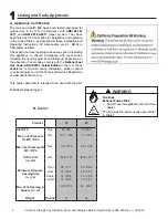
A. Gas Supply Connection

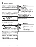
Ensure fittings are of the appropriate size and type on the 

gas line connection. If the tubing has to be cut to length be 

sure to use the proper cutting and flaring tool. Also, be care

-

ful not to crimp the tubing while bending. If the tubing be-

comes crimped, do not use for installation. 

Fire Risk

Explosion Risk

Verify inlet pressures.

•  High  pressure  may  cause  overfire 

condition.

•  Low pressure may cause explosion.

Install regulator upstream of valve if line 

pressure is greater than 1/2 psig.

WARNING

Appliance Preparation 

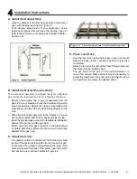
B. Convert to Left Side Gas Piping

•  Remove the brass elbow from the right side.

•  Remove the cap from the left side.

Note: 

Prior to installing the fittings, use Teflon tape or joint 

compound on the male threads.

Note: 

An individual manual shutoff valve (not supplied) is 

required when installing this appliance. The manual shutoff 

valve must be located in an easily accessible area, no more 

than 6 feet from the appliance.

Note: 

Have  the  gas  supply  line  installed  in  accordance 

with local building codes, if any. If not, follow 

ANSI 223.1

Installation should be done by a qualified installer approved 

and/or licensed as required by the locality. (In the Common-

wealth of Massachusetts installation must be performed by 

a licensed plumber or gas fitter.)

Note: 

A listed (and Commonwealth of Massachusetts 

approved) 1/2 in. (13 mm) T-handle manual shut-off valve 

and  flexible  gas  connector  are  connected  to  the  1/2  in. 

(13 mm) control valve inlet.

•  If substituting for these components, please consult 

local codes for compliance.

WARNING

Gas Leak Risk

•  Support control when attaching pipe to 

prevent bending gas line.

WARNING

Fire Risk

Explosion Risk

•  Gas build-up during line purge may 

ignite.

•  Purge should be performed by qualified 

technician.

•  Ensure adequate ventilation.

•  Ensure there are no ignition sources such 

as sparks or open flames.

Fire Risk

Explosion Risk

Personal Injury Risk

An  explosion  could  occur  if  a  connection  is 

made directly to an unregulated propane (LP) 

tank.

WARNING

Joint compound or Teflon tape must be used on all threaded 

male connections to ensure a tight seal.

•  Replace the cap on the opposite end of the burner tube.

•  Install the brass elbow on the left side of the burner.

Summary of Contents for outdoor lifestyles OD-18NG

Page 1: ...ther appliance What to do if you smell gas Do not try to light any appliance Do not touch any electrical switch Do not use any phone in your building Immediately call your gas supplier from a neighbor...

Page 2: ...ention to all cautions and warnings This owner s manual should be retained for future reference We suggest you keep it with your other important documents and product manuals The information contained...

Page 3: ...as Piping 7 C Gas Pressure 8 4 Installation Instructions A Install the Damper Stop 9 B Install the Burner Pan Assembly 9 C Install the Grate 9 D Place Lava Rock 9 E Install the Logs 10 F Adjust the Bu...

Page 4: ...ections In the absence of local codes comply with the National Fuel Gas Code ANSI Z223 1 Latest Edition in the U S If any assistance is required during installation please contact your local dealer or...

Page 5: ...ation consult a qualified installer service agency or the gas supplier WARNING Sharp Edges Wear protective gloves and safety glasses during installation CAUTION C Inspect the Appliance and Components...

Page 6: ...been under water Immediately call a qualified service technician to inspect the appliance and to replace any part of the control system and any gas control which has been under water WARNING Inspect a...

Page 7: ...ote Have the gas supply line installed in accordance with local building codes if any If not follow ANSI 223 1 Installation should be done by a qualified installer approved and or licensed as required...

Page 8: ...are tight Turn on the gas and coat each joint with a non corrosive gas leak check solution Air bubbles will form indicating any leaks DO NOT USE A FLAME OR ANY TYPE OF IGNITION SOURCE TO CHECK FOR LEA...

Page 9: ...r pan assembly in the fireplace The pan should be centered both front to back and side to side Bend the provided gas connector to facilitate its installation between the burner and the gas stub Attach...

Page 10: ...rate this appliance Cleaning Periodic examination and cleaning of the venting system of the fireplace should be done before initial use and at least annually by a qualified agency Fire Risk Explosion...

Page 11: ...ighting the burner follow these instructions exactly B BEFORE LIGHTING smell all around the appliance area for gas Be sure to smell next to the floor because some gas is heavier than air and will sett...

Page 12: ...ilation air is not obstructed front grilles and vent caps Before installing into a solid fuel burning fireplace the chimney and firebox should be inspected and cleaned to remove soot creosote ashes pa...

Page 13: ...ied technician recommended Check Condition of doors surrounds and fronts Obstructions of combustion and ventilation air Condition of logs Condition of firebox Gas connections and fittings Obstructions...

Page 14: ...earth Kits 4004 316 Rev I 01 2022 14 7 7 Reference Materials Service Parts Stainless Hearth Kit Assembly Stainless Grate Assembly 1 2 Outdoor lifestyles by hearth home technologies hearth kits Beginni...

Page 15: ...ch FT 18 1 FT 18 1 1 4 End Cap 4066 157 4066 157 1 5 Brass Elbow 1 2 x 3 8 Flare not shown 10 1037 10 1037 1 7 Orifice BPO 2 26 BPO 2 26 1 8 Damper Stop Assy SRV500 SC SRV500 SC 1 9 Brass Elbow 3 8 x...

Page 16: ...rth Kits 4004 316 Rev I 01 2022 16 B Optional Components Matchlight Burner Hearth Kits FSP 10 SS Conversion kit Matchlight to Safety Pilot LP Specify Size Available for All Models GLHE PACKAGE Gas Log...

Page 17: ...t from HHT regardless of the installation or occupancy date The term Lifetime in the table below is defined as 20 years from the beginning date of warranty coverage for gas appliances 10 years from th...

Page 18: ...ndling devices such as exhaust fans or forced air furnaces or other such causes 6 use of fuels other than those specified in the operation instructions 7 installation or use of components not supplied...

Page 19: ...follow these instructions for safe installation and operation D O N O T D I S C A R D This product may be covered by one or more of the following patents United States 4593510 4686807 4766876 4793322...

Reviews: