background image

53

Hearth & Home Technologies  •  B41L-AU Installation Manual  • 2570-980 Rev. C  •  7/20

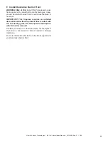
Figure 10.15   CFTF Front Without Outer Decorative Barrier Front 

Trim

CFTF Decorative Barrier Front

Non-Combustible Finish Material 1-6 in. (25-152 mm) Thick


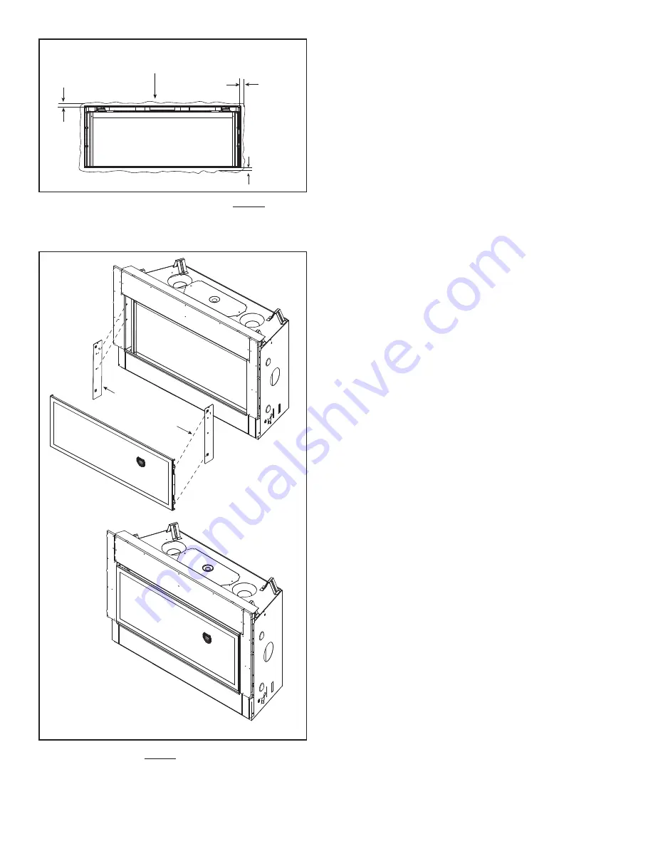
0 IN. / mm 

0 IN. / mm 

  (CFTF) 

0 IN. / mm 

Figure 10.14   Clearances to Appliance Opening Without Outer

                        Decorative Barrier Front Trim

(BOTH SIDES)

(BOTH SIDES)

FACE OF NON-COMBUSTIBLE BOARD 

AUXILIAR

Y HANGING 

BRACKETS

Summary of Contents for B41L-AU

Page 1: ...t reach your gas supplier call the fire department Installation and service must be performed by a qualified installer service agency or the gas supplier WARNING FIRE OR EXPLOSION HAZARD Failure to follow safety warnings exactly could result in serious injury death or property damage DANGER HOT GLASS WILL CAUSE BURNS DO NOT TOUCH GLASS UNTIL COOLED NEVER ALLOW CHILDREN TO TOUCH GLASS A barrier des...

Page 2: ...iance Chase 15 4 Termination Location and Vent Information A Vent Termination Minimum Clearances 16 B Chimney Diagram 17 C Approved Pipe 18 D Use of Elbows 18 E Measuring Standards 19 F Vent Diagrams 20 5 Vent Clearances and Framing A Pipe Clearances to Combustibles 30 B Wall Penetration Framing Firestops 30 C Ceiling Firestop Floor Penetration Framing 31 D Install Attic Insulation Shield 31 6 App...

Page 3: ...__________ Was a conversion performed ___________________________ Leak check performed and inlet pressure verified ___________________________ Verified proper air shutter setting for installation type ___________________________ Finishing Section 10 Pg 46 54 Combustible materials not installed in non combustible areas ___________________________ Verified all clearances meet installation manual req...

Page 4: ... Gas types only through field conversions The allowable Outlet Manifold Gas Pressure ranges are Natural Gas 0 63 0 95 kPa 0 76 kPa nominal and Propane 2 37 2 61 kPa 2 40 kPa nominal Certification testing setpoint values are shown NOTE An inline fuel pressure regulator is recom mended to limit NG inlet pressure to 2 49 kPa and Propane inlet pressure to 3 25 kPa to ensure optimum product performance...

Page 5: ... consisting entirely of steel iron brick tile concrete slate glass or plasters or any combination thereof Materials that are reported as passing ASTM E 136 Standard Test Method for Behavior of Materials in a Vertical Tube Furnace at 750 ºC 1382 F shall be con sidered non combustible materials F Combustible Materials Specification Materials made of or surfaced with wood compressed pa per plant fibe...

Page 6: ...rformed by qualifiedpersonnel Hearth HomeTechnologiesrecommends HHT Factory Trained or NFI certified professionals Figure 2 1 Good Faith Wall Surface Temperatures Above Appliance MEASUREMENTS FROM TOP EDGE OF THE OPENING 6 in 18 in 24 in 30 in 36 in 48 in TO CEILING 42 in 12 in 194 F APPLIANCE FRONT FIREPLACE OPENING 142 F 119 F 110 F 105 F 101 F 98 F 95 F 90 C 61 C 48 C 43 C 41 C 38 C 37 C 35 C 1...

Page 7: ...losion or Electric Shock DO NOT use this appliance if any part has been under water Call a qualified service technician to inspect the appliance and to replace any part of the control system and or gas control which has been under water Carefully remove the appliance and components from the packaging The vent system components and decorative barrier fronts may be shipped in separate packages If pa...

Page 8: ... 4 387 E 33 11 16 856 F 3 1 2 89 G 7 178 H 46 1 2 1181 I 9 13 16 249 J 17 3 4 451 K 1 2 13 L 30 3 4 781 Appliance Dimensions Table U Ø HEAT MANAGEMENT SYSTEMS ACCESS W O V GAS LINE ACCESS Q P C X S T B A LEFT VIEW FRONT VIEW RIGHT VIEW E D F G ELECTRICAL ACCESS H M R N Ø J K I TOP VIEW L 3 3 Framing and Clearances A Appliance Decorative Front Dimension Diagrams Dimensions are actual appliance dime...

Page 9: ...ative barrier front dimensions Use for reference only Figure 3 2 Decorative Barrier Front Dimensions CFTF IMPORTANT This fireplace requires an installed decorative barrier front to prevent direct contact with the hot viewing glass DO NOT operate the fireplace with the barrier removed Decorative barrier front must be ordered at time of fireplace purchase If decorative barrier front is not present c...

Page 10: ...uld vary due to individual design preference It is important to follow the framing and finishing instruc tions step by step to ensure proper placement of fireplace in the surrounding framing finishing materials Figure 3 3 Appliance Locations A E A C TOP VENT ONE 900 ELBOW ALCOVE INSTALLATION D TOP VENT ONE 90 ELBOW B F Refer to Section 10 C for mantel and wall projection information Consider the m...

Page 11: ...H I J K Rough Opening Vent Pipe Rough Opening Height Rough Opening Depth Rough Opening Width Clearance to Room Ceiling Combustible Floor Minimum Hearth Required Behind Appliance Sides of Appliance Front of Appliance Clearance to Ceiling B41L AU in 8 5 8 32 3 4 17 3 4 42 31 0 0 1 2 1 2 36 56 7 8 mm 219 832 451 1067 787 0 0 13 13 914 1445 F G I H E MEASURE FROM TOP OF APPLIANCE OPENING J K Note Head...

Page 12: ... DIMENSIONS A B C D E TRIM KIT INSTALLED PHTRIM LINEAR NO TRIM KIT Required Height of Discharge Opening Height of Discharge Opening Clearance to Top of Discharge Opening Width of Discharge Opening Clearance to Top of Discharge Opening From Bottom of Appliance Clearance from Bottom of Appliance to Bottom of Discharge Opening B41L AU Inches 3 1 2 2 48 36 1 2 73 7 8 71 7 8 millimeters 89 51 1219 927 ...

Page 13: ...GE FRAMING DIMENSIONS A B C D Inside Height Inside Width Outside Height Outside Width PHTRIM 36LINEAR Inches 2 9 16 36 1 2 5 5 8 38 3 8 millimeters 65 927 143 975 Passive Heat Front Discharge PH FRT LINEAR Trim Kit Vent Cover Dimensions Figure 3 6 Passive Heat Front Discharge Vent Cover Dimensions ...

Page 14: ...g Dimensions Passive Heat Side Discharge PH SIDE LINEAR WARNING Risk of Fire DO NOT place combustible objects or combustible materials in non combustible zone Appliance and combustible materials will overheat E B A D C APPLIANCE MAY BE INSTALLED OFF OF FLOOR Side Discharge Air conveyed into the room through two discharge registers one on each side of appliance ROOM CEILING 1 1 2 IN 2 X 4 FRAMING 2...

Page 15: ...19 927 Mesh screen required for front discharge or open top discharge passive heat installations with discharge opening of 3 in 76 mm or greater Framing Dimensions Passive Heat Open Top Discharge PH FRT LINEAR WARNING Risk of Fire Mesh screen required on bottom of discharge opening when discharge opening is greater than 3 in 76 mm Secure mesh to top of framing Open Top Discharge Both sides and the...

Page 16: ... draft problems The chase is an extension of the building thermal envelope To further prevent drafts and air leakage the wall shield and ceiling firestops should be sealed with caulk with a minimum of 300 ºF 149 ºC continuous exposure rating to seal gaps Gas line holes and other openings should be sealed with caulk with a minimum of 300 ºF 149 ºC continuous exposure rating or stuffed with unfaced ...

Page 17: ...this distance may need to be increased Refer to the installation instructions supplied with the decorative cap cover A B 6 in 152 mm minimum up to 20 in 508 mm 18 in 457 mm minimum 20 in 508 mm and over 0 in minimum In a staggered installation with both gas and wood or fuel oil terminations the wood or fuel oil termination cap must be higher than the gas termination cap H MIN MINIMUM HEIGHT FROM R...

Page 18: ...r projections Appliances up to 50 MJ h input 300 200 b From the ground or above a balcony Appliances 32 MJ h and below 300 355 Appliances from 32 MJ h to 53 MJ h 300 410 c From a return wall or external corner 500 300 d From a gas meter M 1000 1000 e From an electricity meter or fuse box P 500 500 f From a drain or soil pipe 150 75 g Horizontally from any building structure unless appliance approv...

Page 19: ...d Horizontal Offset for SLP Elbows Vent Type X Y Inches Millimeters Inches Millimeters SLP 5 127 11 3 4 298 SLP Pipe Effective Length Rise Run Inches Millimeters Inches Millimeters SLP4 4 102 2 3 4 70 SLP6 6 152 4 1 4 108 SLP12 12 305 8 1 2 216 SLP24 24 610 17 432 SLP36 36 914 25 1 2 648 SLP48 48 1219 34 864 SLP6A 3 to 6 76 to 152 2 1 8 4 1 4 54 108 SLP12A 3 to 12 76 to 305 2 1 8 8 1 2 54 216 C Ap...

Page 20: ...See Section 12 A Figure 12 1 for information on effective length of pipe components Horizontal terminations are measured to the outside mounting surface flange of termination cap see Figure 4 6 Vertical terminations are measured to top of last section of pipe See Figure 4 7 Horizontal pipe installed level with no rise MEASURE TO SHADED SURFACE OUTSIDE MOUNTING SURFACE Figure 4 6 Measure to Outside...

Page 21: ...w may be replaced with two back to back 45º elbows When penetrating a combustible wall a wall shield firestop must be installed When penetrating a combustible ceiling a ceiling firestop must be installed Horizontal runs of vent do not require vertical rise horizontal runs may be level Horizontal termination cap should have a 1 4 in 6 mm downward slant to allow any moisture in cap to be released Se...

Page 22: ...CAUTION The SLP HRC SS termination caps are not approved for use with these models May lead to elevated glass temperature that may cause tempered glass breakage V Minimum H1 Maximum B41L AU 90 Elbow Not Allowed 1 ft 305 mm 1 ft 305 mm 2 ft 610 mm 5 ft 1 5 m 3 ft 914 mm 8 ft 2 4 m 4 ft 1 2 m 10 ft 3 0 m 5 ft 1 5 m 15 ft 4 6 m H MAX 15 ft 4 6 m V H MAX 40 ft 12 2 m H1 V1 ...

Page 23: ...HRC SS termination caps are not approved for use with these models May lead to elevated glass temperature that may cause tempered glass breakage V Minimum H1 H2 Maximum B41L AU 90 Elbow Not Allowed 1 5 ft 457 mm 1 ft 305 mm 2 ft 610 mm 5 ft 1 5 m 3 ft 914 mm 8 ft 2 4 m 4 ft 1 2 m 10 ft 3 0 m 5 ft 1 5 m 15 ft 4 6 m H1 H2 MAX 15 ft 4 6 m V1 H1 H2 MAX 40 ft 12 2 m INSTALLED HORIZONTALLY H1 H2 V1 ...

Page 24: ...rmination caps are not approved for use with these models May lead to elevated glass temperature that may cause tempered glass breakage B41L AU V1 Minimum H1 H2 Maximum V2 V1 V2 Minimum 1 5 ft 457 mm 6 ft 1 8 m 2 ft 610 mm 9 ft 2 7 m 3 ft 914 mm 14 ft 4 3 m H1 H2 MAX 14 ft 4 3 m V1 V2 H1 H2 MAX 40 ft 12 2 m No specific restrictions on this value EXCEPT V1 V2 H1 H2 cannot exceed 40 ft 12 2 m H2 H1 ...

Page 25: ...m Top Vent Horizontal Termination continued Risk of Fire This vent configuration can ONLY be used for B41L AU Natural Gas appliances WARNING Figure 4 12 Three Elbows CAUTION The SLP HRC SS termination caps are not approved for use with these models May lead to elevated glass temperature that may cause tempered glass breakage V1 H1 H3 H2 INSTALLED HORIZONTALLY INSTALLED HORIZONTALLY ...

Page 26: ...570 980 Rev C 7 20 Top Vent Vertical Termination No Elbow V1 60 ft Max 18 3 m Note Use SLP Series components only Note If installing a vertical vent termination off the top of the appliance the optional vertical termination baffle may be needed Figure 4 13 V1 ...

Page 27: ...restrictor can be located in the appliance manual bag 1 Remove inner heat shield by removing two wing nuts from top front of heat shield and two screws that se cure the heat shield to back wall of fireplace Retain heat shield and fasteners 2 Center the exhaust restrictor in the open end of the exhaust outlet and secure through the slots on the exhaust restrictor with the two 1 4 in 6 mm self tap p...

Page 28: ...ly Top Vent Vertical Termination continued B41L AU V1 Minimum H Maximum V2 V1 V2 Minimum 1 ft 305 mm 2 ft 610 mm 2 ft 610 mm 3 ft 914 mm 3 ft 914 mm 5 ft 1 5 m 4 ft 1 2 m 7 ft 2 1 m 5 ft 1 5 m 15 ft 4 6 m H MAX 15 ft 4 6 m V1 V2 H MAX 40 ft 12 2 m No specific restrictions on this value EXCEPT V1 V2 H cannot exceed 40 ft 12 2 m H1 V1 V2 ...

Page 29: ...P Series components only B41L AU V1 Minimum H1 H2 Maximum V2 V1 V2 Minimum 1 ft 305 mm 1 ft 305 mm 2 ft 610 mm 2 ft 610 mm 3 ft 914 mm 4 ft 1 2 m 4 ft 1 2 m 6 ft 1 8 m 5 ft 1 5 m 14 ft 4 3 m H MAX 14 ft 4 3 m V1 V2 H1 H2 MAX 40 ft 12 2 m No specific restrictions on this value EXCEPT V1 V2 H1 H2 cannot exceed 40 ft 12 2 m INSTALLED HORIZONTALLY H1 H2 V1 V2 ...

Page 30: ... C 7 20 Note Use SLP Series components only B41L AU V1 MIN H1 MAX V2 MIN H2 MAX V3 MIN 2 1 2 ft 762 mm 4 ft 1 2 m 4 ft 1 2 m 4 ft 1 2 m 3 1 2 ft 1 0 m V1 V2 V3 H1 H2 Maximum 40 ft 12 2 m Figure 4 17 Four 90º Elbows Top Vent Vertical Termination continued V1 H1 V2 V3 H2 ...

Page 31: ...ess than 4 3 8 the existing heat shields must be field trimmed If wall thickness is greater than 7 5 8 in a DVP HSM B will be required SLP Pipe Shown 3 in 76 mm top clearance 1 in 25 mm clearance bottom sides Heat Shield Wall Shield Firestop Heat Shield WALL 3 in 76 mm top clearance 1 in 25 mm clearance around vertical sections B Wall Penetration Framing Firestops Combustible Wall Penetration When...

Page 32: ...he pipe to prevent overheating Figure 5 3 Installing Ceiling Firestop Figure 5 4 Installing the Attic Shield INSTALL ATTIC INSULATION SHIELDS BEFORE OR AFTER INSTALLATION OF VENT SYSTEM CEILING FIRESTOP INSTALLED BELOW CEILING CEILING FIRESTOP INSTALLED ABOVE CEILING ATTIC ABOVE A PIPE SLP A 9 in 229 mm A D Install Attic Insulation Shield WARNING Fire Risk DO NOT allow loose materials or insulatio...

Page 33: ...gement systems installations Provisions must be made in advance to ensure fit within the framing Determine the heat management system s that will be installed Locate the two heat management ports on the top of the appliance Either one or two Heat Zone 240V Gas Kits may be installed See Figure 6 2 Remove the knockouts from the appliance with a tin snips Center the duct collar or passive heat adapte...

Page 34: ...astener per nailing tab Optional Secure the appliance to the floor by inserting two screws through the pilot holes at the bottom of the appliance Risk of Fire Prevent contact with Sagging or loose insulation Insulation backing or plastic Framing and other combustible materials WARNING DO NOT remove standoffs or notch the framing around the appliance standoffs Failure to maintain air space clearanc...

Page 35: ...aside 2 Remove the lower cover panel by removing two screws located on the lower left and right sides of the appliance opening Retain screws Lift the lower cover panel up and out to remove 3 Locate the manual bag assembly and remove the small package containing the 1 1 2 in 38 mm Phillips screws Note Care should be taken when installing screws into the non combustible board DO NOT overtighten scre...

Page 36: ...n 1 2 in 13 mm to hold outer pipe sections together If predrilling holes DO NOT penetrate inner pipe Requirement for Commercial Multi family Multi level ex ceeding two stories or High Rise Applications All outer pipe joints must be sealed using one of the meth ods below including the slip section that connects directly to the horizontal termination cap Apply a bead of silicone sealant 300 ºF 149 º...

Page 37: ...slip section See Figure 7 4 120º Figure 7 5 Securing Vertical Pipe Sections 120º Figure 7 6 Securing Horizontal Pipe Sections C Secure the Vent Sections Vertical runs originating off the top of the appliance with no offsets must be supported every 8 ft 2 44 m after the maximum allowed 25 ft 7 62 m of unsupported rise Vertical runs originating off the rear of the appliance or after any elbow must b...

Page 38: ...7 20 D Disassemble Vent Sections Rotate either section see Figure 7 7 so the seams on both pipe sections are aligned as shown in Figure 7 8 Pull carefully to separate the pieces of pipe Figure 7 8 Align and Disassemble Vent Sections Figure 7 7 Rotate Seams for Disassembly ...

Page 39: ...ocated above the roof SEAL Assemble and Install Storm Collar CAUTION Risk of Cuts Abrasions or Flying Debris Wear protective gloves and safety glasses during instal lation Sheet metal edges are sharp Slide the storm collar onto the exposed pipe section and align brackets Insert a bolt provided through the brackets and install nut Do not completely tighten Slide the assembled storm collar down the ...

Page 40: ... of the existing heat shields using the screws supplied with the extended heat shield Refer to vent components diagrams in the back of this manual Rest the small leg on the extended heat shield on top of the pipe section to properly space it from the pipe section Figure 7 12 Venting Through the Wall Note When using termination caps with factory supplied heat shield attached no additional wall shie...

Page 41: ...ace damaged wire with type 105 ºC rated wire Wire must have high temperature insulation Valve Control Access The valve control cavity is accessible by removing two screws located in the lower right and left corners of the fireplace opening See Figure 8 1 Once finish material has been installed access to the valve control cavity is limited to access through the fire box see Section 9 C Accessories ...

Page 42: ...efore use B Wiring Requirements NOTICE Batteries should only be used as a power source in the event of an emergency power outage Batteries should not be used as a primary long term power source Battery polarity must be correct when installing batteries When using batteries as a power source the 6 volt transformer must be unplugged from the receptacle Do not store batteries in the battery pack when...

Page 43: ...ss type Optimum appliance performance requires proper input pressures Pressure requirements are WARNING Risk of Fire or Explosion High pressure will damage valve Low pressure could cause explosion Verify inlet pressures Verify minimum pressures when other household gas appliances are operating Install regulator upstream of valve if line pressure is greater than 1 2 psig Fire Risk Explosion Hazard ...

Page 44: ...wo screws that secure the pilot assembly to the burner bracket Remove the one screw that secures the burner bracket to the valve plate See Figure 9 2 Gently push the pilot assembly backwards to allow for the burner to be removed 3 Slide burner assembly to the left to disengage the burner tube from the orifice Remove the burner from the appliance 4 Remove the nine screws around the perimeter of the...

Page 45: ...utter to a more closed position If flames are dark orange with smoky tips adjust the shutter to a more open position Figure 9 4 Air Shutter Location Air Shutter Settings Glass Media Option or Driftwood Option Traditional Log Option B41L AU NG 1 8 in 3 mm 3 16 in 5 mm B41L AU LP 1 4 in 6 mm 5 16 in 8 mm D Gas Connection Note Have the gas supply line installed in accordance with local building codes...

Page 46: ...hose consisting entirely of steel iron brick tile concrete slate glass or plasters or any combination thereof Materials that are reported as passing ASTM E 136 Standard Test Method for Behavior of Materials in a Vertical Tube Furnace at 750 ºC The factory supplied board is designed such that its edg es will be at the approximate center of the adjacent fram ing assuming it is 1 1 2 in nominal thick...

Page 47: ... into the non combustible board excessively Set screws flush to the face of the non combustible board See Figure 10 2 and Section 6 D 4 When installing drywall around the appliance install a rectangular hole for the fireplace non combustible board in a single sheet of drywall This will minimize the joints that require finishing adjacent to the fireplace opening Ensure that the 1 8 inch gap is main...

Page 48: ... etc Refer to Figure 10 2 for acceptable screw location and screw length requirements Do not drill or install screws which may penetrate the lower cover panel as this will restrict required access to the glass battery back up and control module See Figure 10 2 Note If the desired look is painted drywall it is recommended that no additional screws are installed into the factory provided non combust...

Page 49: ...ments in millimeters 12 IN MAX 305 mm 1 2 IN 13 mm THICK WALL SHEATHING 14 IN 356 mm MIN BOTTOM OF MANTEL TO TOP OF APPLIANCE OPENING NON COMBUSTIBLE MANTEL 6 IN MAX 152 mm NON COMBUSTIBLE MANTEL APPLIANCE OPENING Non Combustible Mantels Figure 10 5 Minimum Vertical and Maximum Horizontal Dimensions of Non Combustibles Note All measurements in inches Figure 10 6 Combustible and Non Combustible Man...

Page 50: ...N MIN DO NOT INSTALL FINISHING MATERIAL ON THIS SURFACE 2 IN 51 mm MIN OPENING MUST NOT BE BLOCKED CEILING 12 1 4 IN 311 mm 8 3 4 IN 222 mm SIDE DISCHARGE DISCHARGE SLOTS ON BOTH SIDES OF APPLIANCE FRONT DISCHARGE OPEN TOP DISCHARGE COMBUSTIBLE MATERIAL ALLOWED Mesh screen required for front discharge or open top discharge passive heat installations with discharge opening of 3 in 76 mm or greater ...

Page 51: ...1 in 0 25 mm thick See Figure 10 10 NOTICE This one inch maximum not only includes the decorative finish materials marble tile slate etc but also the mortar or adhesive used to attach the decorative finish material The non combustible finish material can be installed up to the fireplace opening FRONT FACE OF FIREPLACE DECORATIVE BARRIER FRONT 1 IN 25 mm MAX FINISHING MATERIAL TOP EDGE Figure 10 9 ...

Page 52: ... is approved for inside fit applications finish material over 1 in 25 mm thick The CFTF decorative barrier front can be installed with or without the outer decorative barrier front trim included with the decorative barrier front See Figure 10 11 If the desired look is to include the outer decorative barrier front trim finishing materials up to 1 3 16 in 30 mm around the fireplace opening See Figur...

Page 53: ...r Decorative Barrier Front Trim CFTF Decorative Barrier Front Non Combustible Finish Material 1 6 in 25 152 mm Thick 0 IN mm 0 IN mm CFTF 0 IN mm Figure 10 14 Clearances to Appliance Opening Without Outer Decorative Barrier Front Trim BOTH SIDES BOTH SIDES FACE OF NON COMBUSTIBLE BOARD AUXILIARY HANGING BRACKETS ...
Page 54: ...RE MESH PASSIVE HEAT DISCHARGE OPENING SEE FIGURES 3 5 3 7 3 8 MINIMUM CLEARANCE TO DISCHARGE OPENING NOTE The TV installation requirements are the same regardless of whether the Passive Heat kit is installed with a top discharge side discharge or open top discharge 71 7 8 IN 1826 mm MIN Appliance may be installed off of floor Good Faith Guidelines for TV Installations Above a Fireplace with Passi...

Page 55: ...e firebox or underneath in the control cavity C Install the Glass Refractory Optional An optional glass refractory kit is available for use with the B41L AU model Install the glass refractory per instructions included with the kit D Install Log Set or Other Optional Media Driftwood Logs Stones Optional log set and other media options are available for use with the B41L AU model Install the log set...

Page 56: ... tab near the front of the basepan will rest in the notch in the front tip of the log See Figure 11 5 Note When Log 3 is correctly positioned on Log 1 the left side of the log will be just outside the left end of the burner See Figure 11 6 Figure 11 4 Place Log 1 Figure 11 5 Place Log 3 Figure 11 6 Place Log 3 1 1 1 1 1 1 3 3 3 3 7 7 7 7 MINERAL WOOL MINERAL WOOL 6 Install Log 6 by placing the rig...

Page 57: ... in front of pilot or directly on burner Do NOT place lava rock in a position that they may fall into area in front of pilot Do NOT use any media other than the lava rock supplied with this kit Do NOT use more than one bag of lava rock per fireplace Do NOT exceed one layer of media on base pan Fireplace will not function properly Delayed ignition could occur WARNING Risk of Asphyxiation or Fumes P...

Page 58: ... bottom two glass latches Use one hand to support the glass at all times 2 Fasten the two upper glass latches one at a time by pulling out and downward into position on the glass assembly Use one hand to support the glass at all times 3 Verify that the top two glass latches are engaged by vi sually verifying that glass latches have engaged both left and right tabs on the glass frame 4 Verify the b...

Page 59: ...rier fronts could cause fireplace to overheat IMPORTANT This fireplace requires an installed decorative barrier front to prevent direct contact with the hot viewing glass DO NOT operate the fireplace with the barrier removed Contact your dealer or Hearth Home Technologies if the barrier is not present or help is needed to properly install one For more information refer to the instructions supplied...

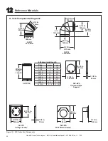
Page 60: ... mm 6 1 2 in 165 mm 9 1 4 in 235 mm SLP45 45 Elbow SLP90 90 Elbow Effective Height Length SLP PIPE SLP HVS Horizontal Pipe Support SLP FS Ceiling Firestop SLP WS Wall Shield Firestop 10 7 8 in 276 mm 8 7 8 in 225 mm 1 1 2 in 38 mm 8 11 16 in 220 mm 8 11 16 in 220 mm 1 1 2 in 38 mm 12 in 305 mm 12 in 305 mm 5 1 2 in 146 mm Effective Height Length Pipe inches mm SLP4 4 102 SLP6 6 152 SLP12 12 305 SL...

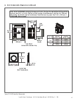
Page 61: ...e heat shield is designed to be used on a wall 4 in to 7 1 4 in 102 mm to 184 mm thick If wall thickness is less than 4 in 102 mm the existing heat shields must be field trimmed If wall thickness is greater than 7 1 4 in 184 mm a DVP HSM B will be required Heat Shield Term Cap Minimum Effective Length Maximum Effective Length Trap1 3 1 8 in 4 3 4 in 79 mm 121mm Trap2 5 1 4 in 9 1 4 in 133 mm 235 m...

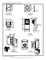
Page 62: ...mm 12 in 305 mm SLP CCS BK Cathedral Ceiling Support Box Black SLP DCF BK Ceiling Firestop Black SLK SNKD Snorkel Termination Cap SLP TVHW Vertical Termination Cap DVP FBHT Horizontal Termination Cap SL 2DVP Required 13 1 2 in 343 mm 28 1 2 in 724 mm 10 11 16 in 271mm 4 3 4 in 121 mm 4 1 8 in 105 mm 17 7 8 IN 454 mm 7 3 8 IN 187 mm 14 IN 356 mm 12 IN 305 mm SLP TB1 Basement Vent Cap A Vent Compone...

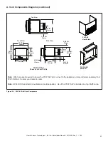
Page 63: ... 241 mm 4 3 4 IN 121 mm 2 1 4 IN 57 mm 1 1 2 IN 38 mm 6 1 4 IN 159 mm Front View Top View Side View PVLP BEK Brick Kit Note Wire harnesses required to power the PVLP SLP AU connect to the appliance and are ordered separately from PVLP SLP AU Contact your dealer to order Figure 12 4 PVLP SLP AU Vent Components Note A PVLP HS heat shield is available and sold separately Use if the PVLP SLP is instal...

Page 64: ... approved optional accessories with this appliance WARNING Risk of Fire and Electric Shock Use ONLY Hearth Home Technologies approved optional acces sories with this appliance Using non listed accessories could result in a safety hazard and will void the warranty Optional Heat Managment Systems After a service technician has installed the Heat Zone 240V or Passive Heat Kit follow the instructions ...

Reviews: