background image

52

52

3-90-30007480

Hearth and Home Technolgies • Oxford Direct/Natural Vent Installation Manual_R3  •  02/19

4021-645J • 08-03-17

3

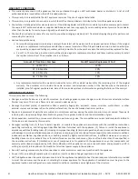
This warranty is void if:

•  The appliance has been over-fired, operated in atmospheres contaminated by chlorine, fluorine, or other damaging chemicals. 

Over-firing can be identified by, but not limited to, warped plates or tubes, deformation/warping of interior cast iron structure or 

components, rust colored cast iron, bubbling, cracking and discoloration of steel or enamel finishes. 

•  The appliance is subjected to prolonged periods of dampness or condensation.

•  There is any damage to the appliance or other components due to water or weather damage which is the result of, but not limited 

to, improper chimney or venting installation.

LIMITATIONS OF LIABILITY

•  The owner’s exclusive remedy and HHT’s sole obligation under this warranty, under any other warranty, express or implied, or in 

contract, tort or otherwise, shall be limited to replacement, repair, or refund, as specified above. In no event will HHT be liable for 

any incidental or consequential damages caused by defects in the appliance. Some states do not allow exclusions or limitation of 

incidental or consequential damages, so these limitations may not apply to you. This warranty gives you specific rights; you may also 

have other rights, which vary from state to state. EXCEPT TO THE EXTENT PROVIDED BY LAW, HHT MAKES NO EXPRESS WARRANTIES 

OTHER THAN THE WARRANTY SPECIFIED HEREIN. THE DURATION OF ANY IMPLIED WARRANTY IS LIMITED TO DURATION OF THE 

EXPRESSED WARRANTY SPECIFIED ABOVE.

Summary of Contents for OXDV30-IPI

Page 1: ...of this or any other appliance WHAT TO DO IF YOU SMELL GAS Do not try to light any appliance Do not touch any electrical switch do not use any phone in your building Leave the building immediately Immediately call your gas supplier from a neighbor s phone Follow the gas supplier s instructions If you cannot reach your gas supplier call the fire department Installation and service must be performed...

Page 2: ...y 40 H Stove Disassembly 40 I Maintenance Frequency 41 8 Wiring Diagrams 42 9 Service Parts List 43 10 Optional Accessories 49 11 Warranty Policy 50 1 Important Safety Information A Massachusetts Safety Information 4 B California Safety Information 4 2 Framing and Clearances A Appliance Dimension Diagram 5 B Installation Requirements 6 C Clearance Requirements 6 D Hearth Requirements 7 E Clearance...

Page 3: ...stallations in the U S and Canada This appliance may be installed in an aftermarket manufactured mobile home where not prohibited by state or local codes WARNING Operation of this heater when not connected to a properly installed and maintained venting system can result in carbon monoxide CO poisoning and possible death The Oxford Direct Vent Room Heater when installed must be electrically grounde...

Page 4: ...EAR OF ALL OBSTRUCTIONS Exemptions The following equipment is exempt from 248 CMR 5 08 2 a 1 through 4 The equipment listed in Chapter 10 entitled Equipment Not Required To Be Vented in the most current edition of NFPA 54 as adopted by the Board and ProductApproved side wall horizontally vented gas fueled equipment installed in a room or structure separate from the dwelling building or structure u...

Page 5: ...tion The Oxford stove is shipped from the factory as a Direct Vent Gas Heater This heater may be converted into a Natural Vent unit in the field If a Natural Vent heater is desired the FSDHAGSLP Draft Hood must be directly installed to the top of the unit according to the installation instructions When the stove is converted to Natural Vent it uses 4 vent pipe For aesthetic purposes the Hearth Hom...

Page 6: ...ommend the use of wallpaper next to this stove Over time radiant heat may cause the wallpaper to shrink or may adversely affect the binders in the wallpaper adhesive WARNING Due to high temperatures the heater should be located out of traffic and away from furniture and draperies The surface of the Heater Is hot when it is in use Young children should be watched carefully when they are in the same...

Page 7: ...ance Direct Vent and Natural Vent Stove Clearances A 4 102 mm ST129c Dutchwest corner specs 01 19 A A Figure 2 3 Parallel installation minimum back and side clearances Parallel Installation Minimum Clearance Direct Vent and Natural Vent Stove Clearances A 4 102 mm B 4 102 mm ST128b Stardance flue centerline 01 19 B A Wall Centerline from Floor Effective Minimum A Wall Thimble 57 1 2 1461 mm HHT Pi...

Page 8: ...e a vertical rise of up to 40 12 m Figure 7 Horizontal termination must also meet the criteria shown in Figures 2 11 and 2 12 Approved vent systems must terminate above and including the heavy line in Figure 2 7 Two 45 elbows may be substituted for each single 90 elbow With a rise between 2 5 one 90 or two 45 elbows may be used Figure 2 7 Horizontal vent termination window Model Fuel Control Max I...

Page 9: ... by loosening the adjustment screw to allow the restrictor plate to slide up or down Figure 2 9 A guide for usage is shown in Figure 2 10 NOTE Some installations may require some adjustment by the installer for optimum flame appearance Optimum flame appearance is a flame that is not subject to tall dirty yellow flames producing soot or flames lifting off of the ember bed ports Restrictor Plate Adj...

Page 10: ...n clearances to keep in mind are shown in Figure 2 11 Important All vent clearances must be maintained Check your vent termination clearances against Figures 2 11 and 2 12 The vent should be placed so that people cannot be burned by accidentally touching the vent surfaces when the stove is operating The vent termination should be located where it cannot be damaged by such things as automobile door...

Page 11: ... h 3kW and 100 000 BTU h 30kW 36 91cm for appliances 100 000 BTU h 30kW 6 15cm for appliances 10 000 BTU h 3kW 9 23cm for appliances 10 000 BTU h 3kW and 50 000 BTU h 15kW 12 30cm for appliances 50 000 BTU h 15kW K Clearance to mechanical air supply inlet 6 1 83m 3 91cm above if within 10 3m horizontally L Clearance above paved sidewalk or paved driveway located on public property 7 2 13m 7 2 13m ...

Page 12: ...ng the FSDHAGSLP the restrictor plate supplied with the stove is not used Outside Corner Inside Corner Termination Clearances Termination clearances for buildings with combustible and noncombustible exteriors G Combustible 6 152 mm Noncombustible 2 51 mm F Combustible 6 152 mm Noncombustible 2 51 mm G Balcony with no side wall M Combustible Noncombustible 12 305 mm M Balcony with perpendicular sid...

Page 13: ...asteners LINK STOVE Trapezoid Termination Kit 3 1 8 4 3 4 SLP TRAP1 Trapezoid Termination Kit 5 1 4 9 1 4 SLP TRAP2 Rear Vent Termination Kit SLP RVTK Vertical Termination cap High Wind includes storm collar SLP TVHW Decorative Wall Thimble Cover SLP WT BK Decorative ceiling firestop black SLP DCF BK Cathedral ceiling support black SLP CCS BK 4 100mm pipe length black SLP4 BK 6 150mm pipe length b...

Page 14: ...ns carefully to maximize stove performance and safety Report damaged parts to your dealer Important Safety Information The termination cap MUST be vented directly to the outside The termination kit MUST NEVER be connected to a chimney flue s servicing a separate solid fuel burning appliance or any other appliances Termination cap MUST NOT be recessed into a wall Figure 3 1 The installation must co...

Page 15: ...regular basis to make sure that no debris is interfering with the airflow Inspect entire venting system to ensure proper function Outside Wall Finishing Material Vinyl Siding etc Figure 3 1 Termination cap on wall General Information The Oxford is approved for installation only with the vent components listed under Section A Venting Requirements Options Follow the vent component instructions exact...

Page 16: ...ection can then be attached to the next pipe section If the slip section is too long the inner and outer flues of the slip section can be cut to the desired length WARNING Risk of Fire Explosion DO NOT break seals on slip sections Use care when removing termination cap from slip pipe If slip section seals are broken during removal of the termination cap vent may leak Secure the Vent Sections Verti...

Page 17: ... Failure to maintain overlap may cause overheating and fire Note For horizontal vent runs through a combustible wall and framing dimensions refer to appliance installation manual Install the Horizontal Termination Cap Attach slip section of cap to last vent section Maintain 1 1 2 overlap between slip and vent sections Note For installations using black pipe slide the decorative wall thimble over t...

Page 18: ...ollars to the center of the wall opening Figure 3 12 Vertical Side Wall Installation NOTE Refer to Figures 2 8 thru 2 10 for restrictor plate adjustments for vertical vent runs 1 Locate vent opening on the wall It may be necessary to first position the stove and measure to obtain hole location Depending on whether the wall is combustible or noncombustible cut opening to size Figure 3 11 For combus...

Page 19: ...s Join the pipes and fasten the snorkel termination to the wall with the screws provided 6 Level the soil to maintain a 4 clearance below the snorkel 7 If the foundation is recessed use extension brackets not supplied to fasten the lower portion of the snorkel Fasten the brackets to the wall first and then fasten to the snorkel with self tapping 8 x 1 2 sheet metal screws Extend the vent pipes out...

Page 20: ...ical rise is required Figure 3 17 Two sets of 45 elbow offsets may be used within the vertical sections From 0 to a maximum of 8 feet 2 5 m of vent pipe can be used between elbows Figure 3 17 SLP HVS supports offsets This application will require that you first determine the roof pitch and use the appropriate starter kit Refer to Venting Components list The maximum angular variation allowed in the...

Page 21: ...onform with local codes and or the current National Fuel Gas Code ANSI Z22 1 For Canadian installations The venting system must conform to the current CSA B149 1 installation code Install the Vent Pipe Apply a bead of sealant around bottom end of inner starter pipe found in bag with logset and attach to stove Apply a bead of sealant around top of inner starter pipe and install the FSDHAGSLP Draft ...

Page 22: ...in located on top of the rear log Figure 3 21 Set the front of the log on the burner and push toward the right side of the firebox the front right corner of the log will touch the side wall of the firebox 4 Place the left log by matching the hole on the underside of the left log with the pin located on top of the rear log Figure 3 21 Set the front of the log on the burner and push toward the left ...

Page 23: ...ing gas line into valve compartment Connect incoming gas line to the 1 2 in 13 mm connection on manual shutoff valve WARNING Risk of Fire Explosion Support control when attaching pipe to prevent bending gas line A small amount of air will be in the gas supply lines WARNING Risk of Fire Explosion Gas build up during line purge could ignite Purge should be performed by a qualified technician Ensure ...

Page 24: ... S Gas connection should be made in accordance with current National Fuel Gas Code ANSI Z223 1 NFPA 54 Since some municipalities have additional local codes be sure to consult your local authority In Canada consult the local authority and CSA B149 1 installation code Air Shutter Adjustment The Oxford is shipped from the factory with the air shutter adjusted to the minimum allowed opening Refer to ...

Page 25: ...hutter May be adjusted up to fully open Burner Rear Injector Air Inlet Figure 4 4 Air shutter adjusted 9 Refasten the two nuts and assemble the burner into the unit by sliding the burner in at an angle with the left side lower than the right side Slide the left side onto the injectors Lower the right hand side down into place Make sure the burner is as far left as possible and the injector shoulde...

Page 26: ...ctors 2 Connect the thermostat wires to the valve Figure 4 6 ST773 handle assy 6 6 03 3 8 Locking Nut Handle Stub Figure 4 7 Insert handle stub into hole in front Secure with 3 8 locking nut ST1126 install stove front Engage steel tabs behind the cast iron bosses Bottom tabs engage notch in the leg Figure 4 8 Install the front plate PILOT ADJ TP TH TPTH ST228 attach switch wires to valve 12 99 Fig...

Page 27: ...condensation will disappear Blue Flames This is a result of normal operation and the flames will begin to yellow as the appliance is allowed to burn for 20 to 40 minutes Odor from Appliance When first operated this appliance may release an odor for the first several hours This is caused by the curing of materials from manufacturing Odor may also be released from finishing materials and adhesives u...

Page 28: ...d appliance junction box to a switched circuit Incorrect wiring will override IPI safety lockout Refer to Figure 5 1 Intellifire Pilot Ignition IPI Wiring Diagram This appliance is equipped with an Intellifire control valve which operates on a 3 volt system Plug the 3 volt AC transformer into the appliance junction box to supply power to the unit OR install two D cell batteries not included into t...

Page 29: ...it OR install 2 D cell batteries not included into the battery pack before use NOTICE Batteries should only be used as a power source in the event of an emergency power outage Batteries should not be used as a primary long term power source Battery polarity must be correct when installing batteries When using batteries as a power source the 3 Volt transformer must be unplugged from the receptacle ...

Page 30: ... prior to operating the appliance See parts list for model number The safety barrier has been designed to work with the doors open or closed 1 Remove screen from packaging 2 Place the two bottom hooks over the bottom edge of the stove opening Figure 5 2 3 Press the screen against the stove snapping the two spring fingers until the screen fits securely in place NOTE It is the responsibility of the ...

Page 31: ... flame patterns are incorrect turn the heater off Contact your dealer or a qualified gas technician for assistance Do not operate the heater until the pilot flame is correct Follow regular maintenance procedures as described in the Cleaning and Maintenance section of this manual E Flame Temperature Adjustment For OXDV30 models which are equipped with HI LO valves flame adjustment is accomplished b...

Page 32: ...all your gas supplier from a neighbor s phone Follow the gas supplier s instructions If you cannot reach your gas supplier call the fire department C Use only your finger to push in the master switch Never use tools If the switch will not function by hand do not try to repair it Call a qualified service technician Force or attempted repair may result in a fire or explosion D Do not use this applia...

Page 33: ...in gas control knob slightly and turn clockwise to OFF Do not force 5 Close control access panel If knob does not pop up when released stop and immediatelycallyourservicetechnicianorgassupplier If after several tries the pilot will not stay lit turn the gas control knob to OFF and call your service technician or gas supplier 11 Replace glass door 12 Turn gas control knob to ON position 13 Turn the...

Page 34: ...ou cannot reach your gas supplier call the fire department C Use only your hand to push in or turn the gas control knob Never use tools If the knob will not push in or turn by hand DO NOT try to repair it call a qualified service technician Force or attempted repair may result in a fire or explosion D DO NOT use this appliance if any part has been under water Immediately call a qualified service techn...

Page 35: ...nd the pilot does not stay on replace the gas valve NOTE An interrupter block not supplied must be used to conduct this test 3 Pilot burning no gas to main burner A Wall switch or wires defective Check wall switch and wires for proper connections Jumper wire across terminals at wall switch if burner comes on replace defective wall switch If okay jumper wires across wall switch wires at valve if bu...

Page 36: ...al module must be replaced If there is a spark at I terminal module is fi ne Inspect pilot assembly for shorted sparker wire or cracked insulator around electrode Replace pilot if necessary Pilot won t light there is no noise or spark No power or power supply installed incorrectly Verify that power supply is installed and plugged into module Check voltage of power supply under load at spade connec...

Page 37: ... pilot burner pilot enclosure or screen if present or any other metal object Poor flame rectification or contaminated flame sensing rod With fixed glass assembly in place verify that flame is engulfing flame sensing rod on left side of pilot hood Flame sensing rod should glow shortly after ignition Verify correct pilot orifice is installed and gas inlet is set to pressure specifications Module is ...

Page 38: ...three distinct flames one engulfing the sensor one engulfing the thermopile and the other reaching to the main burner WARNING Turn off gas before servicing stove It is recommended that a qualified service technician perform these check ups at the beginning of each heating season Figure 6 4 Pilot Flame CO105d Pilot flame 6 07 djt Burner Inspect area around the injector Remove any lint or foreign ma...

Page 39: ...t will give better results than a single heavy coat Clean porcelain enamel surfaces with a soft damp cloth Do not use abrasive cleaning agents If necessary use only a cleaning agent formulated especially for use on porcelain enamel surfaces DANGER HOT GLASS WILL CAUSE BURNS DO NOT TOUCH GLASS UNTIL COOLED NEVER ALLOW CHILDREN TO TOUCH GLASS Un panneau vitré chaud peut causer des brûlures Laissez r...

Page 40: ...sket material to bulk it up 5 Replace the glass frame and front panel as previously described ST179 glass gasket detail 11 99 Figure 7 2 Wrap the gasket material around the outside edge of the glass G Check the Gas Flame Regularly To ensure that the stove is operating properly check the flames periodically to confirms they match Figure 7 3 The flames will be blue during the first 15 20 minutes of ...

Page 41: ...ncy Annually By Service Technician Tools needed Protective gloves Inspect for damaged or missing logs Replace as necessary Verify correct log placement and no flame impingement causing sooting Correct as necessary Burner Ignition and Operation Frequency Annually By Service Technician Tools needed Protective gloves vacuum cleaner whisk broom flashlight voltmeter indexed drill bit set and a manomete...

Page 42: ... thermostat circuit NOTE IFANY OF THE ORIGINAL WIRE AS SUPPLIED WITH THE APPLIANCE MUST BE REPLACED IT MUST BE REPLACED WITH TYPE SF 2 200 WIRE OR ITS EQUIVALENT Thermocouple Safety Limit Switch Valve ST665 Safety Limit Switch wiring 5 29 01 djt Figure 8 2 Draft hood adapter wiring Refer to Section 5 Electrical Information Figure 5 1 FAN JUNCTION BOX FAN POWER CORD Strain Relief Chassis Ground BLK...

Page 43: ...ber when requesting service parts from your dealer or distributor Stocked at Depot ITEM DESCRIPTION COMMENTS PART NUMBER 1 Gas Log Assembly 20003458K 1 1 Rear Log 20003459K 1 2 Right Log 20003460K 1 3 Left Log 20003461K 2 Lava Rock Splinters 57897K Y 3 Top 30001925A 4 Front 30001928A 5 Door 30001929A 6 End Right 30001927A 7 End Left 30001926A 8 Leg 30001930A 9 Manifold Assembly 20003739 Y Addition...

Page 44: ... 15 Thermocouple 24 SRV24D0808 Y 16 Thermocouple 18 RS SRV26D0566 Y 17 Electrode Ignitor w Cable SIT24 10001297 Y 18 Tubing Pilot w Fittings 1 8x24 26D0665 Y 19 Burner Housing Assembly NG LP 20002214K Y Ceramic Burner Tile SRV57803 Y 20 Grate Burner 20002167 21 Ashdoor Handle Assembly 5004241 22 Handle Damper Maple Wood Black 1600664 Y 23 Switch ON OFF 30000874 Y 24 Wiring Harness 10002582 Y 25 Ri...

Page 45: ...tly to consumers Provide model number and serial number when requesting service parts from your dealer or distributor Stocked at Depot ITEM DESCRIPTION COMMENTS PART NUMBER Optional Accessories Fan Kit FK26 Push Button On Off RCB Push Button On Off Timer RCMT Push Button On Off Thermostat RCST Touch Screen On Off Timer No longer available TSMT Touch Screen On Off Thermostat On Off Timer TSST Wired...

Page 46: ...ce Parts OXDV30 IPI Beginning Manufacturing Date Feb 2019 Ending Manufacturing Date Active Oxford Direct Vent Gas Stove With Screen Barrier and IPI Controls Part number list on following page 02 19 1 1 1 2 1 3 2 10 12 11 21 25 26 30 CEMENT 31 1 3 4 6 7 5 8 14 23 24 22 32 27 29 9 20 28 33 13 15 16 17 18 19 34 ...

Page 47: ...001925A 4 Front 30001928A 5 Door 30001929A 6 End Right 30001927A 7 End Left 30001926A 8 Leg 30001930A 9 Manifold Assembly 20003739 Y 10 Glass 1601691 Y 11 Glass Frame Assembly 30000127 Y 12 Gasket Glass Medium Knit 1203702K 13 Pilot Assembly NG SRV2090 012 Y Propane 2090 013 Y 14 Ori ce Hood Front 69 Propane 30000513 Y 54 NG 20000130 Y 54 Propane 20000130 Y 44 NG SRV30000334 Y 15 Valve NG 750 500 ...

Page 48: ...TEM DESCRIPTION COMMENTS PART NUMBER 27 Left Log Bracket 20002165 28 Nut Hex Jam 3 8 16 TOPLK Z Pkg of 10 1203290 10 29 Gasket Base Pan 20002282 Y 30 Gasket Base Pan Inner 20002566 Y 31 Gasket HE Door 1203687A Y 32 Gasket Cement 3oz Tube 1206122 Y 33 Pan Head SL 1 4 20x3 Z Pkg of 10 1201310 10 Magnet Control Door Use common super glue or silicone to attach 1408818 34 Safety Barrier 30007256 Y Touc...

Page 49: ...fan speeds Specifications 115 Volt 60Hz 75 Amps Maintenance The fan itself does not require regular maintenance however periodic cleaning of the fan and the surrounding area is required Installation Refer to the Install the Optional Fan section of this manual Remote Controls The remote control allows you to turn the heater on or off from anywhere in the room Model Functions Controlled RCB Push But...

Page 50: ...upancy of the dwelling or six months after the sale of the product by an independent authorized HHT dealer distributor whichever occurs earlier However the warranty shall commence no later than 24 months following the date of product shipment from HHT regardless of the installation or occupancy date The warranty period for parts and labor for covered components is produced in the following table T...

Page 51: ...eating appliance some changes in color of interior and exterior surface finishes may occur This is not a flaw and is not covered under warranty Damage to printed plated or enameled surfaces caused by fingerprints accidents misuse scratches melted items or other external sources and residues left on the plated surfaces from the use of abrasive cleaners or polishes Repair or replacement of parts tha...

Page 52: ...he result of but not limited to improper chimney or venting installation LIMITATIONS OF LIABILITY The owner s exclusive remedy and HHT s sole obligation under this warranty under any other warranty express or implied or in contract tort or otherwise shall be limited to replacement repair or refund as specified above In no event will HHT be liable for any incidental or consequential damages caused ...

Page 53: ...5353 3 90 30007480 Hearth and Home Technolgies Oxford Direct Natural Vent Installation Manual_R3 02 19 ...

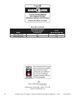
Page 54: ... Vent Installation Manual_R3 02 19 Based on CSA P 4 1 2015 EFFICIENCY RATINGS MODEL ENERGUIDE RATINGS STOVE EFFICIENCY PERCENTAGE D O E AFUE PERCENTAGE OXDV30SP Series 62 7 68 4 OXDV30IPI Series 58 4 68 4 352 Mountain House Road Halifax PA 17032 www vermontcastings com ...

Reviews: