background image

Heatmaster/American Gas Log, LLC •  16-1012 • Rev D.  03/2018

5

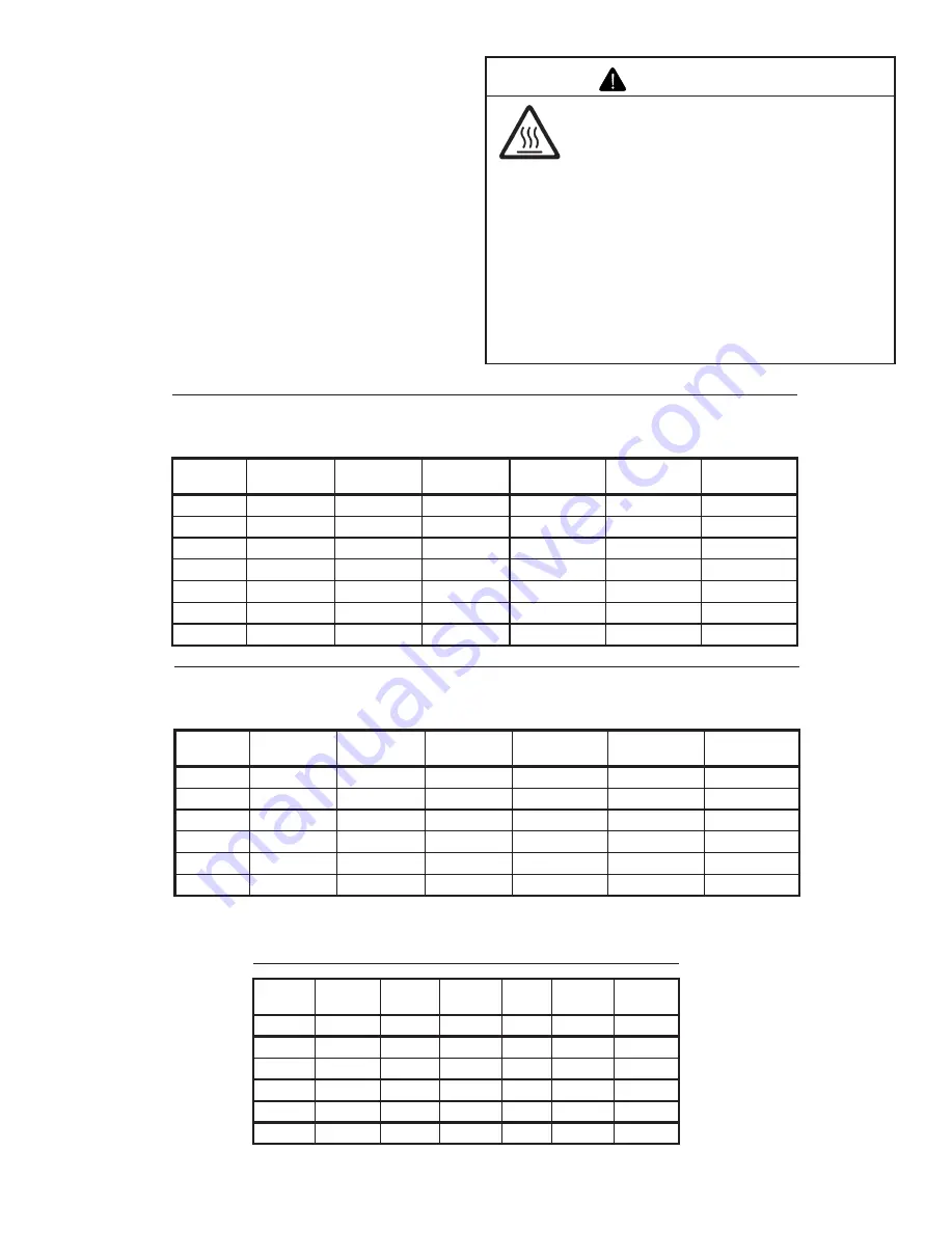
Asphyxiation Risk

This appliance produces carbon monoxide 

(CO).

•  The free opening areas (in square inches) 

of the chimney damper as shown in the 

following tables must be met.

•  User must make sure damper is locked 

open.

•  The  installer  is  responsible  to  ensure 

proper  ventilation  of  flue  gases  before 

appliance is used.

Fire  needs  to  draft  properly  for  safe 

operation.

WARNING

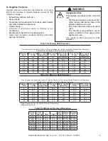
Table 1 for Factory Built Fireplaces

Free Opening Area (in square inches) of Chimney Damper for Venting combustion Products from Decorative 

Appliances for Installation in Solid Fuel Burning Fireplaces.

Chimney Ht. 

(Feet)*

18 in. Log Set 

LP Gas

18 in. Log Set 

Natural Gas

24 in. Log Set 

LP Gas

24 in. Log Set 

Natural Gas

30 in. Log Set 

LP Gas

30 in. Log Set 

Natural Gas

10

28.3

28.3

35.3

not approved

44.2

not approved

15

21.2

21.2

26.4

38.5

32.2

45.4

20

18.1

18.1

22.1

31.2

26.4

37.4

25

15.9

15.9

18.1

27.3

22.9

31.2

30

14.5

14.5

17.3

24.6

20.4

28.3

35

13.2

13.2

15.9

22.1

18.9

25.5

40

12.6

12.6

15.2

20.4

18.1

23.8

Table 2 for Masonry Built Fireplaces

Free Opening Area (in square inches) of Chimney Damper for Venting combustion Products from Decorative 

Appliances for Installation in Solid Fuel Burning Fireplaces.

Chimney Ht. 

(Feet)*

18 in. Log Set 

LP Gas

18 in. Log Set 

Natural Gas

24 in. Log Set 

LP Gas

24 in. Log Set 

Natural Gas

30 in. Log Set 

LP Gas

30 in. Log Set 

Natural Gas

6

41.7

41.7

49.2

64

56.6

71.4

8

38.7

38.7

45.5

59.7

52.4

66.9

10

35.2

35.2

41.7

54.3

48.2

60.2

15

32.0

32.0

37.7

48.8

43.2

54.1

20

28.8

28.8

34.3

44.4

39.8

49.1

30

26.5

26.5

31.2

40.3

35.9

44.5

* Height is measured from the hearth to the top of the chimney.  

   Minimum height is 6 ft.

G. Negative Pressure

Negative pressure results from the imbalance  of air avail-

able  for  the  fireplace  to  operate  properly.  Causes  for  this 

imbalance include:

•  Exhaust fans (kitchen, bath, etc.).

•  Range hoods.

•  Combustion air requirements for furnaces, water heaters 

and other combustion appliances.

•  Clothes dryers.

•  Location  of  return-air  vents  to  furnace  or  air 

conditioning.

•  Imbalances of the HVAC air handling system.

•  Upper  level  air  leaks:  recessed  lighting,  attic  hatch 

opening, duct leaks.

Table 3 for Minimum Fireplace Dimensions

Burner 

Style

Front 

Opening

Depth

Height

Rear 

Width

Natural 

BTU

Propane 

BTU

SBS18

27 In.

16 In.

18 In.

19 In.

44,000

40,000

SBS24

34 in.

20 in.

18 in.

22 in.

73,000

61,000

SBS30

40 in.

20 in.

18 in.

29 in.

80,000

70,000

SBSIII18

32 in.

23 in.

22 in.

21 in.

88,000

80,000

SBSIII24

34 in.

23 in.

22 in.

22 in.

88,000

80,000

SBSIII30

40 in.

23 in.

22 in.

29 in.

92,000

82,000

Summary of Contents for SBS-IPI-18LP

Page 1: ...and liquids in the vicinity of this or any other appliance What to do if you smell gas Do not try to light any appliance Do not touch any electrical switch Do not use any phone in your building Immed...

Page 2: ...This owner s manual should be retained for future reference We suggest you keep it with your other important documents and product manuals The information contained in this owner s manual unless note...

Page 3: ...ore operation Aqualified service technician must perform installation and repair The appliance should be inspected and cleaned annually by a qualified service technician More frequent cleaning may be...

Page 4: ...ting gas line at test pressures above 1 2 psig Close the manual shutoff valve BEFORE pressure testing gas line at test pressures equal to or less than 1 2 psig WARNING Gas Supply Pressure Minimum inle...

Page 5: ...Appliances for Installation in Solid Fuel Burning Fireplaces Chimney Ht Feet 18 in Log Set LP Gas 18 in Log Set Natural Gas 24 in Log Set LP Gas 24 in Log Set Natural Gas 30 in Log Set LP Gas 30 in Lo...

Page 6: ...er of the fireplace and connect to the gas line Follow instructions in F Gas Pressure to check for gas leaks During shipping and handling of this appliance the safety pilot control valve cover may not...

Page 7: ...njury WARNING Figure 6 Placing Vermiculite Figure 5 Sand Lightly place dime size pieces of rock wool evenly on top of the sand and vermiculite to achieve a glowing ember effect See Figure 7 Inspect th...

Page 8: ...ed after the granules are installed DO NOT COVER THE AIR MIXER LOCATED ON THE LOWER LEFT SIDE OF THE BURNER Pour vermiculite into each burner pan to the point where each pan is completely full Level t...

Page 9: ...e in handling CAUTION M Cleaning and Maintenance Instructions Always remember Do not place any combustible material near the appliance Do not place any paper trash or other material on the log set or...

Page 10: ...ble type Can I move or change the position of the logs on my gas log set Certified Log sets should not be altered log placement must be exactly as indicated in the set s installation instructions Can...

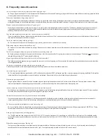
Page 11: ...handle clockwise to the OFF position 3 Wait 5 minutes to clear out any gas Then smell for gas including near the floor If you smell gas STOP Follow B in the safety information above on this label If...

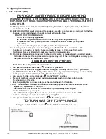
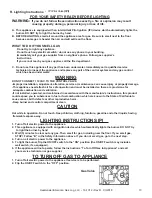
Page 12: ...any part of the control system and any part of the gas control that has been under water 1 STOP Read the safety information listed above 2 Turn gas control handle clockwise to the OFF position 3 Wait...

Page 13: ...r property damage This appliance needs fresh air for safe operation and must be installed so there are provisions for adequate combustion and ventilation If not installed operated and maintained in ac...

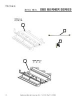
Page 14: ...Heatmaster American Gas Log LLC 16 1012 Rev D 03 2018 14 SBS BURNER SERIES Service Parts 1 1 Parts Diagram SBSIII Burner 18 24 30 SBS Burner 18 24 30 2 3...

Page 15: ...012 Rev D 03 2018 15 Manual Valve Assembly 18 24 30 IPI Valve Assembly 18 24 30 REM Valve Assembly 18 24 30 VAR Valve Assembly 18 24 30 4 5 6 7 8 9 10 11 12 10 11 15 15 16 16 17 17 17 18 18 18 19 20 2...

Page 16: ...MANUAL REM VAR UNITS 15 Pilot Head Assy 09 1007 09 1007 09 1007 1 16 Thermocouple 36 07 1004 07 1004 07 1004 1 Pilot Insulation Pad Not Shown 10 1041 10 1041 10 1041 1 17 Regulator NG 4 0 08 1031 08 1...

Page 17: ...ive pres sure within the structure where the decorative gas log set is installed 4 This Limited Warranty applies only to the components of the Appliance manufactured by Heatmaster American Gas Log LLC...

Reviews: