background image

Heatmaster/American Gas Log, LLC •  16-1012 •Rev D.  03/2018

8

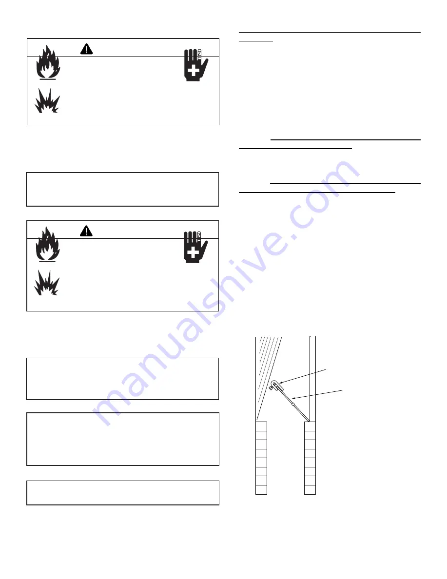
K. Damper Stop Installation Instructions

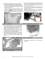
Included in the burner assembly box is a damper stop clamp 

which attaches to the damper as shown (Figure 8). Install 

the clamp to the damper ensuring that the minimum require-

ments (Tables 1 and 2) are achieved. Use a 7/16 in. wrench 

to secure the clamp to the damper. If the damper clamp pro-

vided does not fit your application, other means of securing 

the proper opening must be provided by the installer.

• 

Inspect the pilot burner to ensure it is clear of any 

rock wool

.

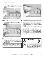
•  Remove the Platinum Bright Embers™ from the package. 

For optimum performance peel each piece apart in layers 

and lightly place on top of the vermiculite and rock wool 

where  the  flame  is  blue. This  will  achieve  the  desired 

realism.

•  The  gas  burns  at  the  point  of  the  least  resistance.  In 

case of an uneven flame pattern it may be necessary to 

adjust the materials in the pans (using an object such as 

a screwdriver) to achieve the desired effect.

•  Place desired amount of lava granules on the floor of the 

fireplace. DO NOT ALLOW THE GRANULES TO COME 

IN CONTACT WITH THE FLAMES. (Lava granules may 

contain moisture which, when heating, may cause it to pop 

out during installation and set-up.) Ensure that the controls 

and  switches  are  unobstructed  after  the  granules  are 

installed. DO NOT COVER THE AIR MIXER LOCATED 

ON THE LOWER LEFT SIDE OF THE BURNER.

  Pour vermiculite into each burner pan to the point where 

each pan is completely full. Level the vermiculite from right 

to left to ensure an even flame pattern. See Figure 6.

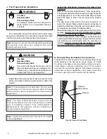
J. For Propane Gas Installation

Fire Risk

Explosion Risk

Personal Injury Risk

An explosion could occur if a connection is 

made  directly  to  an  unregulated  propane 

(LP) tank.

WARNING

•  Lightly place dime size pieces of rock wool evenly on top 

of the vermiculite to achieve a glowing ember effect. See 

Figure 7.

Note: 

Be sure to not cover the pilot assembly (located on 

the  right  side  of  the  burner  pan,  installed  in  the  vertical 

position) with vermiculite.

Note: 

For best results, do not pack down the rock wool. 

The placement of rock wool can have an effect on flame 

pattern and may need to be adjusted to achieve a desired 

appearance.

Fire Risk

Explosion Risk

Personal Injury Risk

Pour vermiculite into each burner pan (LP) to 

the point where each pan is completely full. 

Failure to do so may cause the lighting to be 

delayed and this can be dangerous..

WARNING

Note: 

The  state  of  Massachusetts  requires  that  the 

chimney flue damper, when used with gas logs, be welded 

open  or  completely  removed.  In  the  Commonwealth  of 

Massachusetts  this  appliance  must  be  installed  by  a 

licensed plumber or gas fitter.

Note: 

Log placement photos and instructions are located 

in the log packages.

Damper

Stop Clamp 

Damper

Figure 8 Damper Stop Clamp

Summary of Contents for SBS-IPI-18LP

Page 1: ...and liquids in the vicinity of this or any other appliance What to do if you smell gas Do not try to light any appliance Do not touch any electrical switch Do not use any phone in your building Immed...

Page 2: ...This owner s manual should be retained for future reference We suggest you keep it with your other important documents and product manuals The information contained in this owner s manual unless note...

Page 3: ...ore operation Aqualified service technician must perform installation and repair The appliance should be inspected and cleaned annually by a qualified service technician More frequent cleaning may be...

Page 4: ...ting gas line at test pressures above 1 2 psig Close the manual shutoff valve BEFORE pressure testing gas line at test pressures equal to or less than 1 2 psig WARNING Gas Supply Pressure Minimum inle...

Page 5: ...Appliances for Installation in Solid Fuel Burning Fireplaces Chimney Ht Feet 18 in Log Set LP Gas 18 in Log Set Natural Gas 24 in Log Set LP Gas 24 in Log Set Natural Gas 30 in Log Set LP Gas 30 in Lo...

Page 6: ...er of the fireplace and connect to the gas line Follow instructions in F Gas Pressure to check for gas leaks During shipping and handling of this appliance the safety pilot control valve cover may not...

Page 7: ...njury WARNING Figure 6 Placing Vermiculite Figure 5 Sand Lightly place dime size pieces of rock wool evenly on top of the sand and vermiculite to achieve a glowing ember effect See Figure 7 Inspect th...

Page 8: ...ed after the granules are installed DO NOT COVER THE AIR MIXER LOCATED ON THE LOWER LEFT SIDE OF THE BURNER Pour vermiculite into each burner pan to the point where each pan is completely full Level t...

Page 9: ...e in handling CAUTION M Cleaning and Maintenance Instructions Always remember Do not place any combustible material near the appliance Do not place any paper trash or other material on the log set or...

Page 10: ...ble type Can I move or change the position of the logs on my gas log set Certified Log sets should not be altered log placement must be exactly as indicated in the set s installation instructions Can...

Page 11: ...handle clockwise to the OFF position 3 Wait 5 minutes to clear out any gas Then smell for gas including near the floor If you smell gas STOP Follow B in the safety information above on this label If...

Page 12: ...any part of the control system and any part of the gas control that has been under water 1 STOP Read the safety information listed above 2 Turn gas control handle clockwise to the OFF position 3 Wait...

Page 13: ...r property damage This appliance needs fresh air for safe operation and must be installed so there are provisions for adequate combustion and ventilation If not installed operated and maintained in ac...

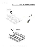
Page 14: ...Heatmaster American Gas Log LLC 16 1012 Rev D 03 2018 14 SBS BURNER SERIES Service Parts 1 1 Parts Diagram SBSIII Burner 18 24 30 SBS Burner 18 24 30 2 3...

Page 15: ...012 Rev D 03 2018 15 Manual Valve Assembly 18 24 30 IPI Valve Assembly 18 24 30 REM Valve Assembly 18 24 30 VAR Valve Assembly 18 24 30 4 5 6 7 8 9 10 11 12 10 11 15 15 16 16 17 17 17 18 18 18 19 20 2...

Page 16: ...MANUAL REM VAR UNITS 15 Pilot Head Assy 09 1007 09 1007 09 1007 1 16 Thermocouple 36 07 1004 07 1004 07 1004 1 Pilot Insulation Pad Not Shown 10 1041 10 1041 10 1041 1 17 Regulator NG 4 0 08 1031 08 1...

Page 17: ...ive pres sure within the structure where the decorative gas log set is installed 4 This Limited Warranty applies only to the components of the Appliance manufactured by Heatmaster American Gas Log LLC...

Reviews: