Hearthstone Quality Home Heating Products, Inc.
Bristol DX Model 8763
30
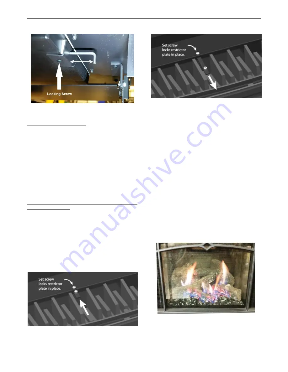
Figure 37
– Locking Screw and Motion Direction
qualified service personnel. Do not attempt to
complete any part of the installation or adjustment of
this unit unless technically qualified to do so.
Restrictor Plate
The restrictor plate is used to control excess draft if
necessary. Controlling the draft also changes the
aesthetics of the flame. The restrictor plate has an
unlimited range of settings (s
ee Figures 38 & 39)
. The
adjustment point is on the top, center of the firebox ,
accessible with the top casting removed.
Restrictor Plate Position
The restrictor plate is factory set in the fully opene d
position for shipping. This ensures proper flames for
a wide variety of vent configurations and efficiency.
The restrictor consists of a sliding plate just below the
venting starter collar on the top rear of the firebox .
Depending on your vent configuration, you may need
to adjust the restrictor plate position to reduce draft.
See Figure 12 on page 17 for settings.
Restrictor Plate Adjustment
Loosen the screw and position the restrictor plate in
the desired location. Tighten the screw to lock in
place.
Figure 38 - Restrictor Fully Closed
Figure 39 - Restrictor Fully Opened (no
restriction)
Burner Flame Appearance
Once the unit is lit, observe the flame pattern and
adjust as necessary. Also, a periodic visual check of
the burner flame should be performed. The burner
flames can be adjusted by means of the air shutter.
To determine if the burner flame needs adjustment, it
is necessary to view the flame pattern with the valve
output at its highest setting. Allow the unit to operat e
for 10 minutes enabling the entire unit to reach
temperature and for the flame pattern to stabilize. The
flame pattern should be similar to the one shown in
Figure 40. There are several guidelines to aid in
determining if the flame pattern is correct:
1. The flame should not be dirty, smoky, sooty, or
lick the top of the stove.
2. The flame should not rise off the burner; this is
called “lifting”.
3. Flames should not impinge heavily on the log set.
They should “fit” through the pre-formed spaces
designed in the log set.
Figure 40
– Typical Burner Flame Appearance


