background image

Hearthstone Quality Home Heating Products, Inc                                                                 

             CHAMPLAIN DV Model 8301  

L

IGHTING 

I

NSTRUCTIONS


1.  Set the on/off/T-stat switch or thermostat to the 

off position. 

2.  Unplug the blower accessory, if so equipped. 

3.  Push in and turn gas control knob clockwise to 

“OFF”. 

 (If not previously lit, the knob should be 

in this position.)


4.  Wait (5) five minutes to clear out any gas.  If you 

then smell gas, STOP! 

Smell all around the 

appliance area for gas. Be sure to smell next to 
the floor because some gases (LPG) are heavier 
than air and will settle on the floor. If you smell 
gas immediately, follow the What To Do If You 
Smell Gas!
 warning on the cover of this Manual.


If you do not smell gas, go to the next step. 

5.  Turn gas control knob counterclockwise to 

“PILOT”. 

6.  Push in control knob all the way and hold in. 

Immediately light the pilot with the gas lighter 
(push in and “click” the piezoelectric spark 
igniter button several times until lit). Continue to 
hold the control knob in for about 20 seconds 
after the pilot is lit. Release the knob and it will 
pop back out. Pilot should remain lit.  If the pilot 
goes out, repeat the operation. 

  If knob does not pop out when released, 

stop and immediately call a qualified service 
technician or gas supplier. 

  If the pilot will not stay lit after several tries, 

turn the gas control knob “OFF” and call a 
qualified service technician or gas supplier. 

7.  Turn gas control knob counterclockwise to “ON”. 

8.  Select “ON” or “T-STAT” position on the on/off/t-

stat switch. 

9.  Shut the gas control valve access door. 

10.  Plug in the blower accessory, if so equipped. 

11.  Set thermostat to “ON” and set the desired 

temperature setting. 

Normally, if the “T-STAT” position was selected, the 
main burner is cycled on and off by the Thermostat 
or the “on”, “off” switch located on the bottom of the 
Thermostat body.  

T

T

URN 

O

FF 

T

HE 

A

PPLIANCE


Turn the gas control knob clockwise to “OFF” 
position, and shut off the gas supply to the valve if 
shutting the unit off for the non-heating season. This 
will improve the overall efficiency of the unit as the 
heat from the pilot is wasted in the summer. Follow 
the lighting instructions outlined on this page when 
putting the unit back into service.


V

ARIABLE 

O

UTPUT 

C

ONTROL


The gas control valve is equipped with a variable 
output control.  This control varies the 

rate 

of heat 

produced by the unit by varying the gas pressure to 
the main burner tube.   

D

AILY 

O

PERATIONS 


The Champlain gas-fired heater is easy to operate. 
The Champlain comes with a standard thermostat. 
Optional remote, or programmable thermostats  are 
available for purchase from your local Hearthstone 
dealer. The desired room temperature is maintained 
with a properly adjusted and installed thermostat.  
By adjusting the variable output control located on 
the gas control valve, the rate of heat output is 
varied to meet the heating requirements of the 
season. Choosing a low flame setting will result in 
longer burn cycles at a reduced output, while 
choosing a high flame setting will result in a shorter, 
hotter burn cycle.  Through trial and error, the 
homeowner can select the optimum flame size for 
their setting, and application. Also available is a 
optional variable speed blower.


Page 7 of 30 

Summary of Contents for Champlain 8301

Page 1: ...er service agency or gas supplier must perform installation and service of this appliance In the Commonwealth of Massachusetts all installation of gas lines and gas fittings must be performed by a lic...

Page 2: ...Intentionally Blank Page 1 of 30...

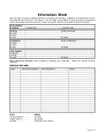
Page 3: ...pt in a safe place as proof of purchase Serial Number Fuel type Natural Gas Liquid Propane Sold by Date of Purchase Address Phone E mail Website Installed by Date of Installation Address Phone E mail...

Page 4: ...ON 9 CLEARANCES TO COMBUSTIBLES 9 HEARTH REQUIREMENT FLOOR PROTECTION 9 VENTING INFORMATION 11 VENTING COMPONENTS CONFIGURATION 11 VENT CONNECTION 11 ACCEPTABLE DIRECT VENT TERMINATION CAP ROOF LOCATI...

Page 5: ...MATERIAL PETS ETC IT IS IMPERATIVE THAT THE CONTROL COMPARTMENTS BURNERS AND CIRCULATING AIR PASSAGES OF THE APPLIANCE ARE KEPT CLEAN AND FREE OF OBSTRUCTIONS S ASSURER QUE LE BR LEUR ET LE COMPARTIME...

Page 6: ...Warranted by Hearthstone Quality Home Heating Products Inc 317 Stafford Ave Morrisville VT 05661 8695 USA www hearthstonestoves com Figure 1 Champlain DV Dimensions Specification NG LP Input rating Bt...

Page 7: ...of the Champlain will reach high temperatures during normal operation Clearances to combustibles must be maintained as specified in the Clearances To Combustibles section of this manual Due to high t...

Page 8: ...ontrol valve access door 10 Plug in the blower accessory if so equipped 11 Set thermostat to ON and set the desired temperature setting Normally if the T STAT position was selected the main burner is...

Page 9: ...st equip pour des altitudes compries entre 0 et 2000 pieds 0 610 m seulement UNPACKING AND INSPECTION Unpack and Inspect for Damage Hearthstone packages the Champlain to withstand normal shipment with...

Page 10: ...ve these two screws and replace them with the two decorative caps provided with the unit 6 To re install reverse the outlined steps above ITEMS REQUIRED FOR INSTALLATION External regulator for LP Phil...

Page 11: ...BY LOCAL CODES THIS APPLIANCE IS ONLY FOR USE WITH THE TYPE OF GAS INDICATED ON THE RATING PLATE THIS APPLIANCE IS NOT CONVERTIBLE FOR USE WITH OTHER GASES UNLESS A CERTIFIED KIT IS USED AVAILABLE TH...

Page 12: ...her direction for installation please refer to the venting instructions provided with the venting components VENT CONNECTION The Champlain Direct Vent Model 8301 is approved for installation only with...

Page 13: ...recommend 12 inches particularly where strong winds prevail H Not to be installed within 15 feet 4 5m above a meter regulator assembly within 3 feet 91cm horizontally from the center line of the regu...

Page 14: ...e elbow so that the twist lock end is pointing straight up Install the 2 pipe section into this elbow by fully inserting it and turning approximately turn clockwise until the two sections are fully lo...

Page 15: ...ll thickness for this configuration is 3 min to 9 max II FIREPLACE VENTING INSTALLATIONS 40 maximum system height without offsets 14 maximum offset refer to Figures 10 12 Maximum rise to run 1 to 5 re...

Page 16: ...to run 1 to 5 The termination must meet the requirements outlined in Figure 8 9 Use a vinyl siding Stand off when installing against vinyl siding Horizontal sections require a 1 4 rise every 12 of ho...

Page 17: ...8301 Figure 13 Venting Configuration and Restrictor Settings VENT RESTRICTOR To adjust your restrictor for maximum flame appearance loosen the phillips head screw and spin the locator found on the re...

Page 18: ...ressure and manifold gas pressure must be tested The gas control valve has built in pressure taps for test gauge connections The supply line pressure must be tested to ensure it meets the minimum pres...

Page 19: ...nd stove parts reduced efficiency and high levels of carbon monoxide If the log set does not fit into the firebox exactly as outlined contact your dealer for assistance INSTALLATION OF THE LOG SET CAU...

Page 20: ...e embers into the burner holes Locate and open the bag of Platinum Bright Embers Pull apart small pieces of the wool and sprinkle over the Charcoal Embers randomly This wool will glow brightly once th...

Page 21: ...r all around the appliance area to check for gas leaks Be sure to test near the floor because some gases LPG are heavier than air and will settle on the floor If you detect gas check for leaks WARNING...

Page 22: ...ONLY A QUALIFIED GAS TECHNICIAN SHOULD DO THE CONVERSION For checking and properly adjusting the manifold pressure refer to the Gas Connection section on page 17 of this manual Leak test before and af...

Page 23: ...he thermocouple and thermopile Turn the unit off by setting the switch to Off and turning off the gas control valve Allow the unit to cool Check and clean any burner ports that are not burning or not...

Page 24: ...ALL WIRES PRIOR TO DISCONNECTION WHEN SERVICING CONTROLS WIRING ERRORS CAN CAUSE IMPROPER AND DANGEROUS OPERATION VERIFY PROPER OPERATION AFTER SERVICING ATTENTION AU MOMENT DE L ENTRETIEN DES COMMAN...

Page 25: ...TER 3160 157 GASKET 6 7211 221 BURNER ASSEMBLY 3160 300 PRIMARY AIR CONTROL GASKET 7211 430 IGNITER ELECTRODE 3170 150 PLATINUM BRIGHT EMBERS 7211 470 THERMOCOUPLE 5300 066 PIEZO BRACKET 7211 601 BOTT...

Page 26: ...3 57010 This appliance is only for use with the type of gas indicated on this rating plate and may be installed in an aftermarket permanently located manufactured mobile home where not prohibited by l...

Page 27: ...embly may be dirty E Clean or replace the pilot assembly 2 Pilot will not stay lit after carefully following lighting instructions A Low or too high gas pressure A Check for proper inlet pressure for...

Page 28: ...er does not come on replace the gas valve C Plugged burner orifice C Remove and check burner orifice clean or replace Note do not use any metal cleaning device as this may damage the orifice 4 Pilot a...

Page 29: ...f gas pressures are correct and the flames stay the same adjust the air shutter for a proper burn 9 Burner flashback Air gas mixture ignites inside the burner near the orifice usually creating a roari...

Page 30: ...ed and signed Warranty Registration Form which is enclosed in the Gas Stove warranty packet to the following address Hearthstone Quality Home Heating Products Inc Warranty Department 317 Stafford Aven...

Reviews: