Hearthstone Quality Home Heating Products, Inc
CHAMPLAIN Model 8302
12
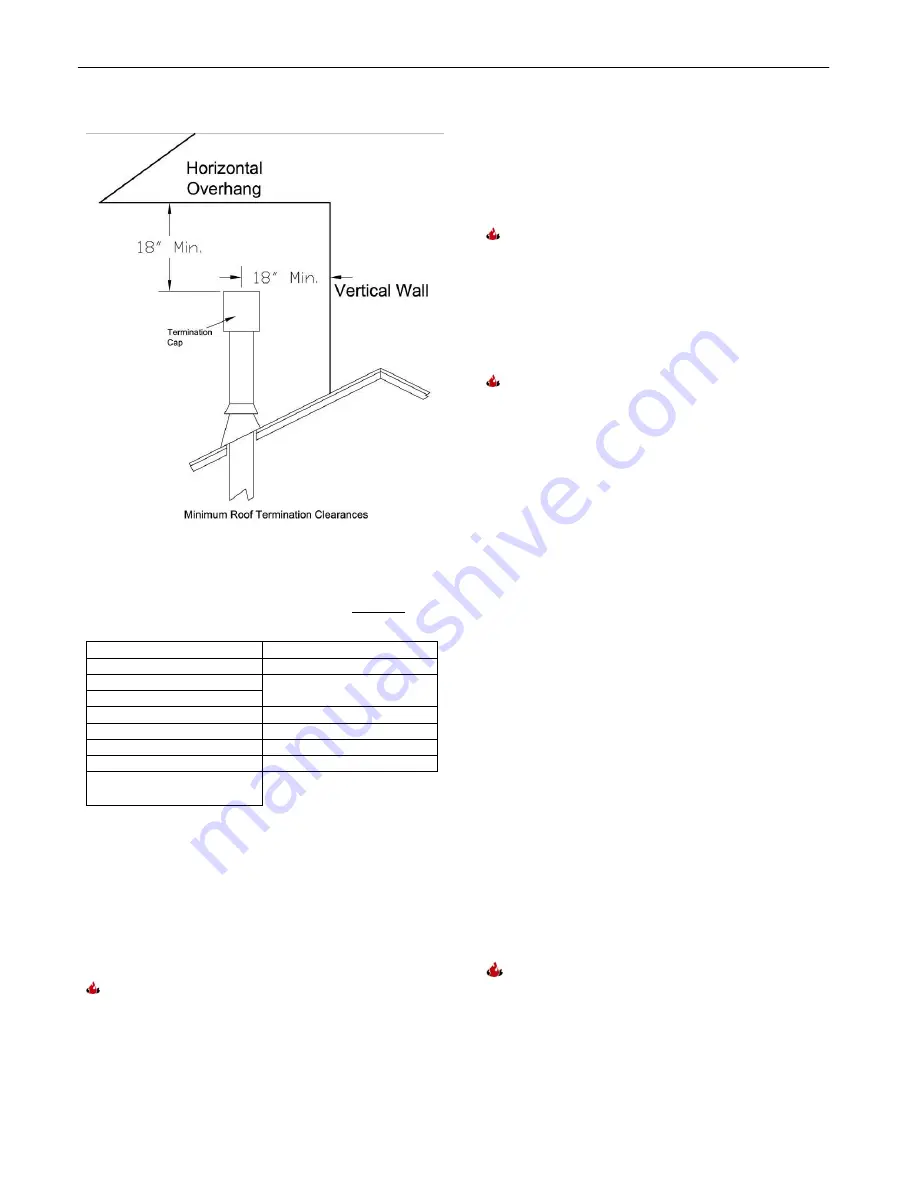
Figure 9: Termination Cap clearances
Approved Venting System Components
(The following are components that are available, BUT NOT
necessary for all installations)
90
0
Elbow
Vertical Vent Cap
45
0
Elbow
36” Snorkel
6" Straight
Vinyl Siding Standoff 4” x
6 5/8"
9" Straight (Simpson only)
12" Straight
Round Ceiling Support
24" Straight
Thimble Covers
36" Straight
Wall thimble
48" Straight
Horizontal Vent Cap
11"-14 5/8" Adjustable
Pipe
Chimney Liner System
Direct-Vent Chimney Liner Termination Kit
Chimney Liner Flex
Co-Linear Flex Connector
Axial to Co-Linear Appliance Connect (Masonry
approved, not to exceed 16’ measured from
stove top).
I
F THE VENT SYSTEM IS DISASSEMBLED FOR ANY
REASON
,
IT MUST BE REINSTALLED PER THE
INSTRUCTIONS PROVIDED FOR IN THE INITIAL
INSTALLATION OR IN THIS MANUAL
.
Vent Configuration Options
I.
S
TANDARD
H
ORIZONTAL
I
NSTALLATION
Kit #93-65000)
Note:
Install the 45º elbow over the outer collar.
Place the elbow so that the twist lock end is
pointing straight
up. Install the 2’ pipe section
into this elbow by fully inserting it, and turning
approximately ¼ turn clockwise until the two
sections are fully locked. Install the 90º elbow in
similar fashion with the opening pointing to the
rear.
Note:
Ensure there is no wiring or plumbing in
the chosen wall location.
Move the stove and pipe assembly back until the
90º elbow is flush to the wall. Ensure t
he 2’ vertical
pipe is still parallel to the wall. Draw a circle around
the pipe where it touches the wall. Use the center
of this circle as the center point of the 10”
x
10”
square wall pass through.
Cut and frame the wall for the vent pipe.
Install the
horizontal vent termination on the outside of the
wall. Ensure both of the retaining straps extend
through the wall pass through to the inside of the
wall.
Before attaching the vent termination to the outside
of the house, run a bead of non-hardening mastic
around the outside edges, between the vent
termination and the wall. The arrow on the end cap
should point up. Secure the cap to the wall with the
appropriate screws.
Put the adjustable (11”-14”) pipe into the horizontal
vent cap, (the vent pipe must extend into the
horizontal vent cap a minimum of 1 ¼”). Move the
stove and vent pipe into position, insert the
adjustable (11”-14”) pipe into the 90° elbow, twist
lock it.
Secure the straps from the horizontal vent
termination to the interior pipe with two sheet metal
screws, keeping the screws as close to the wall
thimble as possible. Bend or cut the excess
strapping so the thimble cover will fit properly.
Screw the thimble cover to the wall.
The adjustment range for wall thickness for
this configuration is 3”min to 9”max.
II.
F
IREPLACE
V
ENTING
I
NSTALLATIONS
-40' maximum system height (without offsets)
-14' maximum offset
(refer to Figures 10 - 11)
Summary of Contents for Champlain 8302
Page 45: ...44 07044 2 RATING LABEL...


