Hearthstone Quality Home Heating Products, Inc.
Stowe 3 Model 8323
19
GAS CONNECTIONS
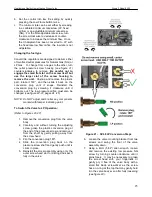
When threads are tightened, the valve must be held
at the designated clamping areas
(see figure 18).
DO NOT apply pressure to top casting or plastic
cover.
Connection Main Gas (Tubing connections)
1. Do NOT use pipe joint compound or
Teflon®/PTFE tape.
2. Slip nut and ferrule over
tubing.
3. Slide nut and ferrule into place, and insert
tubing into inlet/outlet connection until it
bottoms. Turn until finger-tight.
4. Use a wrench to tighten nut about 1 turn beyond
finger tight.
Connection Main Gas (Pipe Connections)
1. Do NOT use Teflon®/PTFE tape.
2. Pipe to be inserted into the valve must be the
proper thread length and to gauge. Thread
that IS cut too long can cause distortion or
malfunction if inserted too deeply.
3. Apply a moderate amount of approved
pipe\sealant to the pipe only, leaving the
two end threads bare.
3. Connect pipe to valve inlet and outlet.
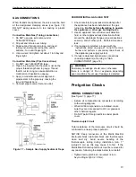
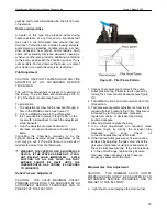
Figure 17
– Sample Gas Supply Sediment Traps
PERFORM INITIAL GAS LEAK TEST
1. Check carefully for gas leaks immediately after
the appliance has been installed and the gas
turned on.
Do this before attempting to operate
the appliance or other gas burning device.
1. Use an approved non-corrosive leak detection
fluid, or other approved leak detection method,
around the diaphragm flanges, pipe connections,
seal cap, and all other joints. Bubbles indicate a
leak.
2. If no leakage is detected, proceed with the
instructions listed on page 21 to light the main
burner and perform a secondary leak check of
the appliance gas supply system.
5. If a leak is detected, tighten pipe connections
(including adapters) according to "GAS
CONNECTIONS" (page 18).
WARNING
Absolutely no leakage should occur, otherwise
there is a danger of fire or explosion depending
upon conditions. Never use if leakage is detected.
Pre-Ignition Checks
WIRING CONNECTIONS
(See
figure 15
, page 17)
• Assure all components are connected according
to the wiring diagram.
• When GV60 components are installed, make
sure they are not exposed to dirt, oil. grease or
other chemical agents.
• Do NOT permit foreign particles under plastic
cover.
Thermocouple Circuit
Total resistance of thermocouple circuit should be
minimized to ensure proper operation.
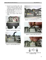
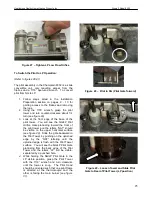
NOTICE: Keep connection of the Mertik Maxitrol
interrupter block interrupter block and thermocouple
clean and dry. Avoid severe bending of the
thermocouple tubing during installation (min. 1"
radius:2.5 cm) as this may cause it to fail. If the
Mertik Maxitrol interrupter block must be removed for
any reason, following the steps below to re-install:
• Tighten interrupter block into valve1/4 turn
beyond finger tight (2...3 Nm).
Summary of Contents for Champlain 8302
Page 45: ...44 07044 2 RATING LABEL...


