background image

Hearthstone Quality Home Heating Products, Inc.


Stowe 3 Model 8323  

26 


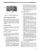
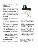
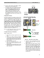
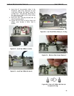
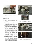
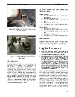
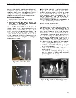
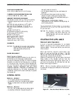
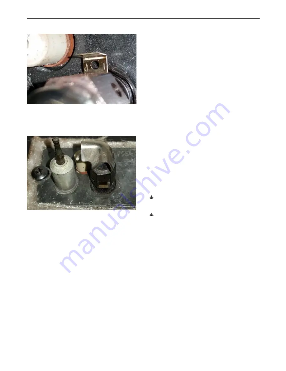
      Figure 30 

– Pilot in LP (LP text visible to rear 

of Pilot Tower) 


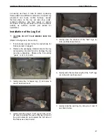
      Figure 31 

– Pilot in LP (slide gate to rear of 

Pilot Tower) 


Initial Adjustments 
 

Once  the  Champlain  is  set  in  place,  connected  and 
assembled  as  described  in  the  Clearances  To 
Combustibles, 

Venting 

Components 

Configurations, 

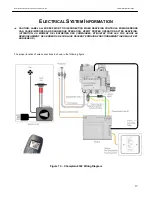
Electrical 

Connections, 

Log 

Placement  and  Maxitrol  GV60  Control  System 
Features & Gas Supply Connections sections of this 
manual, the unit is ready to be lit and adjusted to its 
particular  installation.  Hearthstone  tests  each  unit 
prior  to  shipment,  so  ignition  should  take  place 
without  issue.  However,  a  number  of  small 
adjustments  may  be  necessary  to  compensate  for 
variations in gas pressure, altitude, and other factors 
particular to each installation.  Read pages 28-30 to 
complete installation specific setup. 


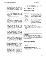
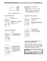
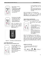
TO  SHUT  DOWN  THE  APPLIANCE  AND 
TURN OFF GAS 

 
Remote Control: 

1.  Push  the  OFF  button  on  the  remote  once 

See page 33).


2.  Remove valve access panel. 
3.  Turn  the  ON/OFF  switch  on  the  valve  to 

OFF. 

4.  Replace valve access panel. 
5.  Turn the gas supply valve to the off position. 

 
Manual Mode: 

1.  Remove valve access panel. 
2.  Turn the Main Valve Knob clockwise to OFF. 
3.  Turn  the  ON/OFF  switch  on  the  valve  to 

OFF. 

4.  Replace valve access panel. 
5.  Turn the gas supply valve to the off position. 


FINAL CHECK 

 
Observe  several  complete  cycles  to  ensure  proper 
operation.    During  these  cycles  the  electronics  will 
determine the optimum ignition sequence timing. 


Log Set Placement


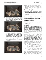
CAUTION:  FRAGILE!  HANDLE  LOG  SET  WITH 
CARE.  ALWAYS  WEAR  GLOVES  AND  SAFETY 
GOGGLES WHILE HANDLING THE LOG SET. 


WARNING: FAILURE TO POSITION THE PARTS IN 
ACCORDANCE  WITH  THESE  DIAGRAMS  OR 
FAILURE  TO  USE  ONLY  PARTS  SPECIFICALLY 
APPROVED WITH THIS APPLIANCE MAY RESULT 
IN  PROPERTY  DAMAGE  OR  PERSONAL  INJURY. 

AVERTISSEMENT.  RISQUE  DE  DOMMAGES  OU 
DE  BLESSURES  SI  LES  PIÈCES  NE  SONT  PAS 
INSTALLÉES CONFORMÉMENT À CES SCHÉMAS 
ET  OU  SI  DES  PIÈCES  AUTRES  QUE  CELLES 
SPÉCIFIQUEMENT  APPROUVÉES  AVEC  CET 
APPAREIL SONT UTILISÉES. 


Place only the ceramic log set supplied with the unit 
in  the  firebox.  Do  not  place  any  other  ceramic  logs, 
wood  logs,  or  other  materials  in  the  firebox.    If  the 
log set is damaged or broken contact your dealer for 
replacement.  The ceramic logs will last a long time; 
however,  they  will  break  if  subjected  to  rough  or 
improper handling. Exact positioning of the log set is 
required  in  order  to  obtain  a  pleasing  flame  pattern 
and  efficient  combustion.    Incorrect  log  placement 
may  cause  carbon  build-up;  excess  thermal  stress 
on  the  log  set  and  stove  parts,  reduced  efficiency, 
and high levels of carbon monoxide. Position the log 

Summary of Contents for Champlain 8302

Page 1: ...service agency or gas supplier must perform installation and service of this appliance In the Commonwealth of Massachusetts all installation of gas lines and gas fittings must be performed by a licen...

Page 2: ...pply Connections 18 Gas Connections 19 Initial Leak Check 19 Pre Ignition Checks 19 Initial Lighting Instructions 21 Remote Ignition Instructions 21 Manual Ignition Instructions 21 Pilot Adjustment 22...

Page 3: ...nt lip lifting slightly and pulling forward free of the stove Set panel aside on a soft surface Locate and grasp receiver body Pull receiver straight forward from the mounting bracket firmly but slowl...

Page 4: ...pt in a safe place as proof of purchase Serial Number Fuel type Natural Gas Liquid Propane Sold by Date of Purchase Address Phone E mail Website Installed by Date of Installation Address Phone E mail...

Page 5: ...Room 1511 Boston Massachusetts 02202 Manufactured and Warranted by Hearthstone Quality Home Heating Products Inc 317 Stafford Ave Morrisville VT 05661 8695 USA www hearthstonestoves com Figure 1 Cham...

Page 6: ...tter on remote control Part Description 8302 0010NP Matte Black 8302 0020NP Brown Enamel Read this Owner s Manual Operate and maintain this gas heater according to the instructions in this manual For...

Page 7: ...on the rating plate This appliance is not convertible for use with other gases unless a certified kit is used Cet appareil doit tre atilis uniquement avec les types de gas indiqu s sur la plaque sign...

Page 8: ...burner material supplied with the Champlain is damaged or parts are missing they must be replaced with the same or approved Hearthstone replacement parts These components affect the combustion qualit...

Page 9: ...0 et 2000 pieds 0 610 m seulement Items Required for Installation External regulator for propane LP only LP conversion kit for propane only Piping which complies with local codes Pipe sealant approve...

Page 10: ...ont panel by lifting up and off of the stove body Set aside on a soft surface Figure 3 Front Panel Removal 3 Remove glass by rotating retention clips up until clear of the clip slot Lean the glass awa...

Page 11: ...S WHICH THROUGH TESTING IN AN INDEPENDENT LABORATORY TO ANSI AND CSA STANDARDS WILL PREVENT FIRE OR SPONTANEOUS COMBUSTION WE DO NOT CONTROL THE COMBUSTIBLE MATERIALS EXPOSED TO HEAT BY THIS PRODUCT T...

Page 12: ...odel 8302 is approved for installation only with the vent connecting components listed in this manual Use the following instructions along with the pipe manufacturer s instructions to complete the ins...

Page 13: ...lumbing in the chosen wall location Move the stove and pipe assembly back until the 90 elbow is flush to the wall Ensure the 2 vertical pipe is still parallel to the wall Draw a circle around the pipe...

Page 14: ...ON VENTING CONFIGURATIONS A minimum of 24 rise is required with or w o offsets 40 maximum system height without offsets Maximum rise to run 1 to 5 The termination must meet the requirements outlined i...

Page 15: ...Hearthstone Quality Home Heating Products Inc CHAMPLAIN Model 8302 14 Figure 12 Approved DV Venting Alternate Configurations for Vertical Termination...

Page 16: ...lity Home Heating Products Inc CHAMPLAIN Model 8302 15 Figure 13 Venting Configuration and Restrictor Settings To adjust your restrictor for optimum flame appearance follow the instructions in Restric...

Page 17: ...m CAN We strongly recommend 12 inches particularly where strong winds prevail H Not to be installed within 15 feet 4 5m above a meter regulator assembly within 3 feet 91cm horizontally from the center...

Page 18: ...ERRORS CAN CAUSE IMPROPER AND DANGEROUS OPERATION VERIFY PROPER OPERATION AFTER SERVICING ATTENTION AU MOMENT DE L ENTRETIEN DES COMMANDES TIQUETEZ TOUS LES FILS AVANT LE D BRANCHEMENT DES ERREURS DE...

Page 19: ...R GLEMENTS SELON LES CODES D INSTALLATION CAN CGA B149 NFPA Code and Hearthstone require the use of a dedicated sediment trap just upstream of the unit Damage to the valve or other components due to...

Page 20: ...rosive leak detection fluid or other approved leak detection method around the diaphragm flanges pipe connections seal cap and all other joints Bubbles indicate a leak 2 If no leakage is detected proc...

Page 21: ...ows for better line of sight see notice below 3 When the RF receiver is placed in the appliance the surrounding metal can reduce reception considerably The position of the antenna on the receiver also...

Page 22: ...leak is detected tighten pipe connections including adapters according to GAS CONNECTIONS page 18 Manual Ignition Optional 1 Remove orange ignition wire from Control module and insert onto Piezo Igni...

Page 23: ...y go out if the pilot flame is too small or misdirected away from the thermopile WARNING THE CONTROL HAS AN INTERLOCK DEVICE IF THE STOVE HAS BEEN LIT IT WILL NOT RELIGHT AGAIN IMMEDIATELY AFTER SHUTT...

Page 24: ...ockwise until it bottoms out The low pressure orifice must also be changed see figure 22 27 pages 24 25 NOTE Do NOT adjust and or alter any components marked with tamper indicating paint To Switch the...

Page 25: ...in the valve snug it down until it stops turning by turning clockwise 9 Swing the valve mounting bracket back up into its original position 10 Tighten the two front mounting screws and assure valve b...

Page 26: ...Gate protruding toward the front of the pilot tower and the letters NAT should be visible on the upper horizontal surface see figure 28 Slide the gate backward in the Pilot Tower by pushing on the up...

Page 27: ...N OFF switch on the valve to OFF 4 Replace valve access panel 5 Turn the gas supply valve to the off position FINAL CHECK Observe several complete cycles to ensure proper operation During these cycles...

Page 28: ...s in this section 1 If not already opened follow the instructions for firebox access on page 9 2 Remove the packaging material around the log set assembly Be careful not to damage the log set when unp...

Page 29: ...cast iron panels are re installed follow start up procedure outlined below Air Shutter The air shutter is used to regulate the air to gas combustion mixture which in turn influences the size and color...

Page 30: ...tions cannot be corrected through air shutter adjustment an adjustment must be made to the gas supply pressure Supply line manifold gas line pressure adjustments must be performed by qualified service...

Page 31: ...estrictor Fully Open Detail baffle removed for clarity Figure 36 Restrictor Adjuster Arm Detail Maxitrol GV60 Control System Features NOTE REMOVE THE MODESTY PANEL BELOW THE FRONT CASTING FOR ACCESS T...

Page 32: ...commended Low battery indicator on handsets with display Battery replacement is recommended after 2 years Batteries Receiver 4 x 1 5V AA quality alkaline recommended Low battery indication frequent be...

Page 33: ...will ignite after the Main Valve knob is turned past the minimum setting Once the main burner is on continue turning the Main Valve knob until the desired flame height is reached 10 If the Main Burne...

Page 34: ...tton C to decrease flame height or to set appliance at pilot flame For fine adjustment tap button A or C Designated Low Fire and High Fire Double click small flame button LO will be displayed NOTE Fla...

Page 35: ...but no flame press and hold the small flame button and turn to Pilot flame NOTE The light bulb icon is displayed during light dimmer setting only 8 seconds after the light dimmer has been set the han...

Page 36: ...F and adjusts fan speed NOTE To turn OFF fan press small flame until all 4 speed bars disappear Nighttime Setback Temperature Mode Appliance must be in standby mode pilot ignited The room temperature...

Page 37: ...press SET button to scroll to TEMP mode sun icon Hold the SET button until the set temperature on the screen flashes Press large flame button to increase Daytime Set Temperature Press small flame but...

Page 38: ...sun icon displayed and the time flashes Set the hour by pressing the large flame button Set the minutes by pressing the small flame button Setting P1 OFF Time Select Timer Mode by briefly pressing th...

Page 39: ...Day Shut Off CSA version The system shuts off the fire completely if there is no change in flame height for 5 days NOTE Before the next ignition there is a 2 minute waiting period Routine Maintenance...

Page 40: ...qualified service personnel as described on page 22 Complete the cleaning procedure by carefully placing the log set within the firebox as described on pages 26 28 Reattach the glass and front panel t...

Page 41: ...ass from the glass frame by drilling out the four 1 8 rivets that lock the glass in place Pull the glass away from the frame and set it aside If replacing gasket only 1 Remove the existing gasket from...

Page 42: ...XCHANGER BASE 5301 080 OUTLET RESTRICTOR CLIP 2310 860 HEAT EXCHANGER 5701 925H STARTER COLLAR 2310 240 EXHAUST BAFFLE 7000 027 THERMOCOUPLE INTERRUPTER 3030 036 GLASS 7000 360 REMOTE CONTROL 3160 080...

Page 43: ...will not stay lit after carefully following lighting instructions A Low or too high gas pressure B Faulty connections C Pilot dirty or plugged D Thermocouple damaged E Thermocouple Interrupter circuit...

Page 44: ...locked the rate at which the exhaust leaves draft determines the rate at which the combustion air is delivered Poor draft results in insufficient air delivery or a restricted exhaust Correct air intak...

Page 45: ...44 07044 2 RATING LABEL...

Page 46: ...d will be warranted under the terms of the limited warranty for a period not to exceed the remaining term of the original limited warranty or one year whichever is longer Parts Hearthstone will replac...

Page 47: ...rials ash grates and glass 4 Damage resulting from installation modification alteration repair or service of the appliance by any party other than an authorized Hearthstone dealer a Dealer or their de...

Page 48: ...ealer service call The Original Purchaser should refer to the Dealer Network search engine contained on Hearthstone s Web site www hearthstonestoves com if the original dealer is not available to find...

Reviews: