Hearthstone Quality Home Heating Products, Inc.
CHAMPLAIN Model 8303
22
If knob does not pop out when released,
stop and immediately call a qualified service
technician or gas supplier.
If the pilot will not stay lit after several tries,
turn the gas control knob “OFF” and call a
qualified service technician or gas supplier.
7.
Turn gas control knob counterclockwise to “ON”.
8.
Select “ON” or “T-STAT” position on the on/off/t-
stat switch.
9. Shut the gas control valve access door.
10. Plug in the blower accessory, if so equipped.
11. Set
thermostat to “ON” and set the desired
temperature setting.
Normally, if the “T-STAT” position was selected, the
main burner is cycled on and off by the Thermostat
or the “on”, “off” switch located on the bottom of the
Thermostat body.
T
O
T
URN
O
FF
T
HE
A
PPLIANCE
Turn the gas control knob clockwise to “OFF”
position, and shut off the gas supply to the valve if
shutting the unit off for the non-heating season. This
will improve the overall efficiency of the unit as the
heat from the pilot is wasted in the summer. Follow
the lighting instructions outlined on this page when
putting the unit back into service.
V
ARIABLE
O
UTPUT
C
ONTROL
The gas control valve is equipped with a variable
output control. This control varies the
rate
of heat
produced by the unit by varying the gas pressure to
the main burner tube.
D
AILY
O
PERATIONS
The Champlain gas-fired heater is easy to operate.
The Champlain comes with a standard thermostat.
Optional remote, or programmable thermostats are
available for purchase from your local Hearthstone
dealer. The desired room temperature is maintained
with a properly adjusted and installed thermostat.
By adjusting the variable output control located on
the gas control valve, the rate of heat output is
varied to meet the heating requirements of the
season. Choosing a low flame setting will result in
longer burn cycles at a reduced output, while
choosing a high flame setting will result in a shorter,
hotter burn cycle. Through trial and error, the
homeowner can select the optimum flame size for
their setting, and application. Also available is a
optional variable speed blower.
Air Shutter
The air shutter is used to regulate the air-to-gas
combustion mixture, which in turn influences the size
and color of the flames. The air shutter is factory
positioned in the general location needed for testing
the unit with natural gas (NG) and minimum venting.
However, if the unit is not burning as well as it
should in your installation, then the air shutter may
need adjusting.
To determine if the air shutter needs adjustment, it is
necessary to view the flame pattern with the burner
output set at its highest setting. Allow the unit to
operate for at least 10 minutes to allow the entire
unit to reach operating temperature, and for the
flame pattern to stabilize. Generally, the more air
(open shutter) in the mixture, the bluer the flame.
Less air (closed shutter) results in a more yellow
flame, but too little air will result in incomplete
combustion, low efficiency and a dirty burn. There
are two simple guidelines to aid in determining the
correct flame pattern:
1. If the flame just above the surface of the
burner or at the base of the logs is
completely blue, the air shutter may be open
too far.
2. If the flame is dirty, sooty or licks the top of
the baffle, the air shutter may be closed too
far.
Some conditions cannot be corrected through air
shutter adjustment; an adjustment must be made to
the gas supply pressure or by changing the
restriction plate setting. Qualified service personnel
must perform supply line/manifold gas line pressure
adjustments and restrictor plate adjustments. Do not
attempt to complete any part of the installation or
adjustment of this unit unless technically qualified.
Air Shutter Adjustments
WARNING: THE ADJUSTING BOLT IS HOT!
WARNING: THE AIR SHUTTER IS FACTORY SET
AND ONLY A QUALIFIED GAS TECHNICIAN
SHOULD MAKE ADJUSTMENTS.
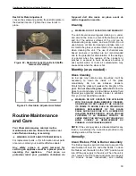
The air shutter is adjustable while the stove is
burning. Loosen the lock nut on the adjusting bolt
located in the lower rear center of the stove. Move
the bolt in or out to adjust the flame pattern
(see
figures 19-21).
Turn the bolt in to open the air
shutter, and turn it out to close the shutter. When

