background image

Hearthstone Quality Home Heating Products, Inc.


CHAMPLAIN Model 8303


23 


the  flame  pattern  is  correct,  hold  the  adjusting  bolt 
head  still  with  a  wrench  and  tighten  the  locking  nut 
to the body of the stove.  


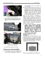
Figure 19 

– Air Shutter Open 


Figure 20 

– Air Shutter Closed 

Note: 

Very little movement is needed to substantially 

change  the  burn  and  flame  patterns.  Some 
conditions  cannot  be  corrected  through  air  shutter 
adjustment; an adjustment must be made to the gas 
supply  pressure.  Supply  line/manifold  gas  line 
pressure  adjustments  must  be  performed  by 
qualified  service  personnel.    Do  not  attempt  to 
complete any part of the installation or adjustment of 
this unit unless technically qualified to do so. 
 

Burner Flame Appearance 
 

Once  the  unit  is  lit,  observe  the  flame  pattern  and 
adjust as necessary.  Also, a periodic visual check of 
the  burner  flame  should  be  performed.  The  burner 
flames can be adjusted by means of the air shutter.  
To  determine  if  the  burner  flame  needs  adjustment, 
it  is  necessary  to  view  the  flame  pattern  with  the 
valve  output  at  its  highest  setting.  Allow  the  unit  to 

operate  for  10  minutes  enabling  the  entire  unit  to 
reach  temperature  and  for  the  flame  pattern  to 
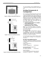
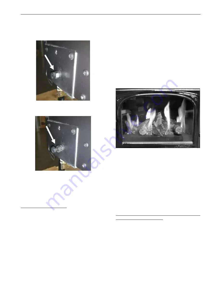
stabilize.  The  flame  pattern  should  be  similar  to  the 
one shown in 

figure 21

. There are several guidelines 

to aid in determining if the flame pattern is correct: 

1.  The  flame  should  not  be  dirty,  smoky,  sooty,  or 

lick the top of the stove. 

2.  The flame should not rise off the pan burner; this 

is called “lifting”. 

3.  Flames  should  not  impinge  heavily  on  the  log 

set.  They  should  “fit”  through  the  pre-formed 
spaces designed in the log set. 


Figure 21 

– Typical Burner Flame Appearance 


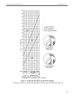
Restrictor Plate 

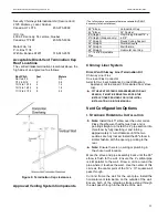
The restrictor plate is used to control  excess draft if 
necessary.  Controlling  the  draft  also  changes  the 
aesthetics  of  the  flame.  The  restrictor  plate  has  a 
large  range  of  unlimited  settings 

(see  figures  22  & 

23).

  The  adjustment  point  is  on  the  left  side  of  the 

firebox (from front). 

Restrictor Plate Position 

The  restrictor  plate  may  be  factory  set  in  the  fully 
closed  position  for  shipping.  If  so,  set  to  the  fully 
opened  position.  This  ensures  proper  flames  for  a 
wide  variety  of  vent  configurations  and  efficiency. 
The restrictor plate consists of a rotating flap in front 
of  the  firebox  exhaust  port  behind  baffle  plate. 
Depending  on  your  vent  configuration,  you  may 
need  to adjust the restrictor plate position to reduce 
draft.  


Summary of Contents for Champlain 8303

Page 1: ...service agency or gas supplier must perform installation and service of this appliance In the Commonwealth of Massachusetts all installation of gas lines and gas fittings must be performed by a licen...

Page 2: ...Page 1 of 35 Intentionally Blank...

Page 3: ...pt in a safe place as proof of purchase Serial Number Fuel type Natural Gas Liquid Propane Sold by Date of Purchase Address Phone E mail Website Installed by Date of Installation Address Phone E mail...

Page 4: ...irement Floor Protection 9 Venting Information 10 Venting Connection 10 Approved Systems 11 Minimum Venting 12 Electrical System Information 16 Gas Supply Connections 17 Gas Connections 17 Initial Lea...

Page 5: ...Room 1511 Boston Massachusetts 02202 Manufactured and Warranted by Hearthstone Quality Home Heating Products Inc 317 Stafford Ave Morrisville VT 05661 8695 USA www hearthstonestoves com Figure 1 Cham...

Page 6: ...will remain appealing while providing years of quality performance The installation must conform to local codes or in the absences of local codes the current National Fuel Gas Code ANSI Z223 1 NFPA 5...

Page 7: ...E COMPARTIMENT DES COMMANDES SONT PROPRES VOIR LES INSTRUCTIONS D INSTALLATION ET D UTILISATION QUI ACCOMPAGNENT L APPAREIL Hot Surfaces Certain exposed surfaces of the Champlain will reach high tempe...

Page 8: ...their absence the latest edition of THE NATIONAL FUEL GAS CODE ANSI Z223 1 NFPA 54 or CAN CGA B149 Installer l appareil selon les codes ou r glements locaux ou en l absence de tels r glements selon le...

Page 9: ...ALL OR PUT INTO SERVICE A DAMAGED OR INCOMPLETE HEATER Remove the shrink wrap and other packaging materials taking care not to damage the stove s finish Inspect the Champlain for visible or concealed...

Page 10: ...either the unit s or the vent pipe s minimum clearance depending on whether the installation calls for vertical rise within the room or a rear exit through the wall vent pipe Ensure you consider the...

Page 11: ...ENSURE NO WIRING OR PLUMBING IS IN THE CHOSEN LOCATION CAUTION DO NOT RECESS VENTING TERMINATIONS INTO A WALL OR SIDING Note If you need further direction for installation please refer to the venting...

Page 12: ...it Chimney Liner Flex Co Linear Flex Connector Axial to Co Linear Appliance Connect Masonry approved not to exceed 16 measured from stove top IF THE VENT SYSTEM IS DISASSEMBLED FOR ANY REASON IT MUST...

Page 13: ...cover will fit properly Screw the thimble cover to the wall The adjustment range for wall thickness for this configuration is 3 min to 9 max II FIREPLACE VENTING INSTALLATIONS 40 maximum system height...

Page 14: ...Hearthstone Quality Home Heating Products Inc CHAMPLAIN Model 8303 13 Figure 12 Approved DV Venting Alternate Configurations for Vertical Termination...

Page 15: ...lity Home Heating Products Inc CHAMPLAIN Model 8303 14 Figure 13 Venting Configuration and Restrictor Settings To adjust your restrictor for optimum flame appearance follow the instructions in Restric...

Page 16: ...m CAN We strongly recommend 12 inches particularly where strong winds prevail H Not to be installed within 15 feet 4 5m above a meter regulator assembly within 3 feet 91cm horizontally from the center...

Page 17: ...ERRORS CAN CAUSE IMPROPER AND DANGEROUS OPERATION VERIFY PROPER OPERATION AFTER SERVICING ATTENTION AU MOMENT DE L ENTRETIEN DES COMMANDES TIQUETEZ TOUS LES FILS AVANT LE D BRANCHEMENT DES ERREURS DE...

Page 18: ...ng system at test pressures equal to or greater than psig Over pressurizing can damage the control resulting in leakage or control malfunction NOTICE A QUALIFIED TECHNICIAN MUST CONNECT THE HEATER TO...

Page 19: ...in a fire or explosion GAS CONNECTIONS Connection Main Gas Tubing connections 1 Do NOT use pipe joint compound or Teflon PTFE tape 2 Slip nut and ferrule over tubing 3 Slide nut and ferrule into place...

Page 20: ...rough or improper handling Exact positioning of the log set is required in order to obtain a pleasing flame pattern and efficient combustion Incorrect log placement may cause carbon build up excess t...

Page 21: ...o use all of the Charcoal Embers Keep the rest for use in the future Do not drop the embers into the burner holes Locate and open the bag of Platinum Bright Embers Pull apart small pieces of the wool...

Page 22: ...st engulf the thermopile so that the thermopile can generate sufficient milli voltage 325 to 500 mv to power the millivolt gas control valve Before lighting smell or use a gas detector all around the...

Page 23: ...r can select the optimum flame size for their setting and application Also available is a optional variable speed blower Air Shutter The air shutter is used to regulate the air to gas combustion mixtu...

Page 24: ...minutes enabling the entire unit to reach temperature and for the flame pattern to stabilize The flame pattern should be similar to the one shown in figure 21 There are several guidelines to aid in de...

Page 25: ...tial for discoloration of the castings or enamel when the residue of the cleaners or polishes is exposed to heat Excessive buildup of dust spider webs or room air contamination may cause odors when th...

Page 26: ...e inspection par un technicien professionnel avant d tre utilis et au moins une fois l an par la suite Des nettoyages plus fr quents peuvent tre n cessaires si les tapis la literie et cetera produisen...

Page 27: ...R CAUTION DO NOT CLEAN THE GLASS WHILE THE UNIT IS HOT Venting Components Venting should not need to be disassembled for normal cleaning However if venting is required to be removed for any reason thi...

Page 28: ...EXCHANGER BASE 7000 350 ORIFICE BURNER NG 31 SPUD 2310 860 HEAT EXCHANGER 7210 103 IGNITOR 23X0 040 TOP CASTING 7211 332 PILOT ASSEMBLY 23X0 440 FRONT CASTING 7211 320 VALVE NG 3030 036 GLASS 7211 01...

Page 29: ...fter sitting for off season summer pilot assembly may be dirty E Clean or replace the pilot assembly 2 Pilot will not stay lit after carefully following lighting instructions A Low or too high gas pre...

Page 30: ...embly If the meter reading is OK but the burner does not come on replace the gas valve C Plugged burner orifice C Remove and check burner orifice clean or replace Note do not use any metal cleaning de...

Page 31: ...Clear obstructions B3 Clear obstructions C If gas pressures are correct and the flames stay the same adjust the air shutter for a proper burn 9 Burner flashback Air gas mixture ignites inside the bur...

Page 32: ...Hearthstone Quality Home Heating Products Inc CHAMPLAIN Model 8303 31 07044 2 RATING LABEL...

Page 33: ...during the limited warranty period will be warranted under the terms of the limited warranty for a period not to exceed the remaining term of the original limited warranty or one year whichever is lon...

Page 34: ...nt gaskets baffles refractory materials ash grates and glass 4 Damage resulting from installation modification alteration repair or service of the appliance by any party other than an authorized Heart...

Page 35: ...ance for repair or to schedule a Dealer service call The Original Purchaser should refer to the Dealer Network search engine contained on Hearthstone s Web site www hearthstonestoves com if the origin...

Reviews: