Hearthstone Quality Home Heating Products, Inc.
Bari Model #8180
V
ENTING
C
OMPONENTS
&
C
ONFIGURATION
Do not vent the Bari jointly with any other solid fuel
or gas appliance. Vent the Bari directly to the
outside of the building using a proper termination as
listed in this manual. The only types of venting pipe
approved for use with your Bari Direct-Vent stove
are those listed in this manual. The venting
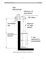
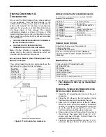
configuration diagram is shown in
Figure 8
. After
determining the proper venting configuration for your
stove, select the vent system that will accommodate
your installation.
CAUTION: ENSURE NO WIRING OR PLUMBING IS
IN THE CHOSEN LOCATION.
CAUTION: DO NOT RECESS VENTING
TERMINATIONS INTO A WALL OR SIDING.
Note:
If further direction is needed for installation,
please refer to the venting instructions, which are
provided with the venting components.
A
CCEPTABLE
D
IRECT
-V
ENT
T
ERMINATION
C
AP
R
OOF
L
OCATIONS
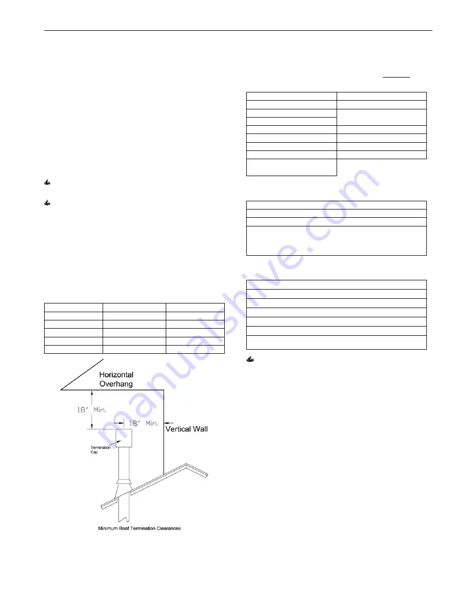
The vent/air intake termination clearances above the
high side of an angled roof are as follows:
Roof Pitch
Feet
Meters
Flat to 6/12
1
0.3
7/12 to 9/12
2
0.6
10/12 to 12/12
4
1.2
13/12 to 16/12
6
1.8
17/12 to 21/12
8
2.4
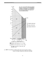
Figure 9: Termination Cap clearances
A
PPROVED
V
ENTING
S
YSTEM
C
OMPONENTS
(The following are components that are available, BUT NOT
necessary for all installations)
90
0
Elbow
Vertical Vent Cap
45
0
Elbow
36” Snorkel
6" Straight
9" Straight (Simpson only)
Vinyl Siding Standoff 4” x
6 5/8"
12" Straight
Round Ceiling Support
24" Straight
Thimble Covers
36" Straight
Wall thimble
48" Straight
Horizontal Vent Cap
11"-14 5/8" Adjustable
Pipe
C
HIMNEY
L
INER
S
YSTEM
Direct-Vent Chimney Liner Termination Kit
Chimney Liner Flex
Co-Linear Flex Connector
-Axial to Co-Linear Appliance Connect
(Masonry
approved, not to exceed 16’ measured from the
stove top
)
M
INIMUM
V
ENT
K
IT
Vent connector (Provided with unit)
24” Straight Pipe
90° elbow
12” Straight pipe
Wall Thimble Cover
Wall Thimble
Horizontal Vent Termination Cap
Dry fit your venting and take a measurement.
Pipe dimensions will vary by manufacturer
and supplier.
H
ORIZONTAL
T
ERMINATION
M
INIMUM
V
ENTING
K
IT
I
NSTALLATION
I
NSTRUCTIONS
1. Install the 24” straight section on top of the vent
connector.
2. Place the 90° elbow on the 24” section. Facing
the direction expected to penetrate the wall.
3. Attach the 12” straight section to the 90° elbow.
Move the stove and pipe assembly backwards
until the 12” straight is flush against the wall. Pull
up on the pipe to ensure that there is a ¼” per
foot rise coming out of the stove to the wall.
4. Draw a circle around the pipe. Use the center of
this circle as the center point of the 10” x 10”
square wall pass through. Cut and frame the
wall pass through opening.
5. Place the interior wall thimble into the 10” x 10”
wall pass through. Secure it with 4 screws (not
14

