background image

HearthStone Quality Home Heating Products, Inc.


MODENA 8140 Gas-Fired Direct-Vent                           


16


CAUTION: Lighting the Modena for the first time 
and adjustments to the unit should be performed by 
qualified service personnel. 


This appliance is designed only for use with the type(s) of 
fuel gas indicated on the rating plate. This appliance is not 
convertible for use with other gases, unless a certified kit is 
used. 


Cet appareil doit être atilisé uniquement avec les types de 
gas indiqués sur la plaque signalétique. Ne pas l’utiliser 
avec d’autres gas sauf si un kited conversion certifié est 
installé. ) 


S

MOKE AND 

F

UMES 

W

ARNING


When lit for the first time, the Modena will emit some 
smoke and fumes.  This is normal “off-gassing” of the 
paints and oils used in the manufacturing and assembly of 
the unit.  Open windows to vent the room if necessary. The 
off-gassing and fumes will subside after the first 10 to 20 
minutes of operation. 


O

DORS AND 

I

MPURITIES


A heater of this type may produce other odors during heater 
operation due to impurities that may exist in the immediate 
area. Sources of impurities can be cleaning solvents, paint 
solvents, cigarettes, candles, smoke, pet hair, dust, 
adhesives, new carpet, and/or textiles. Such odors usually 
dissipate. However, opening a window or otherwise 
providing additional ventilation to the area can alleviate the 
condition quickly. If any odor persists, remove potential 
sources, or contact your dealer or an authorized service 
technician. 


P

ILOT 

L

IGHT


The Modena has a piezoelectric spark igniter (the black 
push button located next to the gas control valve behind the 
door), which ignites the pilot light by means of a spark at 
the pilot light assembly.  


D

N

OT 

L

IGHT 

P

ILOT OR 

B

URNER 

B

H

AND


Never attempt to light the pilot or main burner by hand with 
a match or lighter. If, after repeated attempts, the pilot light 
fails to light using the piezoelectric igniter, discontinue 
operation; turn off the gas at the gas control valve, and 
immediately contact qualified service personnel for 
assistance. 


P

REPARE 

F

OR 

L

IGHTING


Prepare for the lighting procedure by adjusting the 
thermostat (if equipped) to its lowest setting or OFF 
position. If the gas control knob is not in the OFF position, 
turn the knob fully clockwise to OFF. Locate the variable 
output control knob and turn it fully clockwise to the 
highest setting. 


Prior to lighting the unit for the first time, wait 5 minutes to 
allow any residual gas within the unit to dissipate. Smell all 

around the appliance area for gas. Be sure to smell next to 
the floor because some gases (LP) are heavier than air and 
will settle on the floor. If you do not smell gas after this 
five-minute period, proceed with the lighting procedure. If 
you do smell gas, DO NOT proceed with the lighting 
procedure. Instead, 

immediately refer to the What to Do 

If You Smell Gas Warning, on the cover of this manual. 


NOTE: The valve control has an interlock device. After 
shutting off all gas flow, the pilot burner cannot be relit 
until the thermocouple has cooled, releasing the 
electromagnet (approx. 60 seconds). The gas control 
knob is designed to operate by hand. Do not use any 
tools during this operation. Damaged knobs may result 
in serious injury. 


I

NITIAL 

A

DJUSTMENTS


Once the Modena is set in place, connected and assembled 
as described in the “Clearances To Combustibles”, 
“Venting Components & Configurations,” “Electrical 
Connections”, and “Gas Supply and Connections” sections 
of this manual, the unit is almost ready to light for the first 
time. The manufacturer tests each unit prior to shipment, so 
ignition should take place without failure. However, a 
number of small adjustments may be necessary to 
compensate for variations in gas pressure, altitude, and 
other factors particular to each installation. 


V

ARIABLE 

O

UTPUT 

C

ONTROL


The gas control valve is equipped with a variable output 
control. This control varies the rate of heat produced by the 
unit by varying the gas pressure to the TEK Burner. A 
combination of heat output and the thermostat setting affect 
the length of the burn cycle. If your stove cycles on and off 
too often, first try reducing the burn cycle by turning the 
HI/LOW knob, on the control valve, to a lower setting. 
Using the variable output control, the heat output of the unit 
can be reduced for mild fall and spring months, or 
maximized for the colder winter months. This adjustment 
can be made by the homeowner as necessary by turning the 
variable output control knob to “HI”, “LO” or any setting in 
between. 


L

IGHTING 

I

NSTRUCTIONS


NOTE: 

The gas control knobs and the piezo igniter are 

located behind the control valve access door, under the 
front of the unit. 

1.


STOP! Read the What To Do If You Smell Gas! 
Warning (on the cover of this manual). Ensure the 
front door is closed, and the lock screws are in 
place. 

2.


Set the on/off/remote switch or thermostat to the 
“OFF” position.  

3.


Push in and turn the gas control knob clockwise to 
“OFF”. 

 (If not previously lit, the knob should be in this 

position.)


4.


Wait (5) five minutes to clear out any gas.  If you then 
smell gas, STOP! 

Smell all around the appliance area 

for gas. Be sure to smell next to the floor because some 

Summary of Contents for Hase-Modena 8140

Page 1: ...alified installer service agency or gas supplier must perform installation and service of this appliance In the Commonwealth of Massachusetts all installation of gas lines and gas fittings must be per...

Page 2: ...Keep your original receipt in a safe place as proof of purchase Serial Number Fuel type check one Natural Gas Liquid Propane Sold by Phone Date of Purchase Installed by Phone Date of Installation Gas...

Page 3: ...e providing years of quality performance WARNING ENSURE ONLY AN NFI CERTIFIED SERVICE TECHNICIAN INSTALLS AND REPAIRS THIS APPLIANCE A QUALIFIED SERVICE TECHNICIAN MUST INSPECT THE APPLIANCE BEFORE US...

Page 4: ...g and flammable material Certified for use by Board of State Examiners of Plumbers and Gasfitters 100 Cambridge Street Room 1511 Boston Massachusetts 02202 SPECIFICATIONS LISTED AS Gas Fired Direct Ve...

Page 5: ...If you note continuous condensation on the window glass or dripping water from any part of the unit or venting system chimney immediately discontinue operation of the unit and contact qualified servi...

Page 6: ...kits and components are supplied separately Failure to use the venting components specified by Hearthstone QHHP Inc will void your warranty and could result in inefficient or unsafe operating conditio...

Page 7: ...ll as full access for periodic cleaning and servicing Caution These clearances represent minimum distances in all cases which through testing in an independent laboratory to ANSI and CSA standards wil...

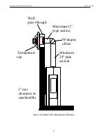
Page 8: ...e Heating Products Inc Modena Model 8140 8 1 rear clearance to combustible Minimum12 pipe section Wall pass through Termination cap 90 degree elbow Minimum 24 pipe section Figure 3 Minimum Vent Config...

Page 9: ...HearthStone Quality Home Heating Products Inc Modena Model 8140 9 Acceptable Direct Vent TERMINATION Cap locations Figure 4 Termination Location Clearances...

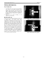
Page 10: ...nt configurations Controlling the draft also changes the aesthetics of the flame The restriction plate consists of a rotating shutter in the flue connector This shutter is attached to a rod that protr...

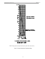
Page 11: ...HearthStone Quality Home Heating Products Inc Modena Model 8140 11 NOTE These positions are based on lab results and can have some variance Figure 7 Venting Configurations Restriction Settings...

Page 12: ...nnector Co Axial to Co Linear Appliance Connect Masonry approved not to exceed 16 measured from the stove top MINIMUM VENT KIT Vent connector Provided with unit 24 Straight 90 degree elbow 12 Straight...

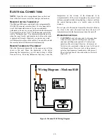
Page 13: ...REMOTE THERMOSTAT PLACEMENT Place the thermostat transmitter in the same room or living space as the unit Since the transmitter is the device measuring the temperature you will want to keep it off th...

Page 14: ...flexible line to avoid undue mechanical load on the valve and to ease thread alignment but refer to local codes CAUTION Check Gas Type GAS SUPPLY Isolate the Modena from the gas supply piping system b...

Page 15: ...r assistance INSTALLATION OF THE FIRE STONE SET Follow the order of the following photos in order to install the stone set Stone set shown in white for better view actual stones will be dark gray 1 In...

Page 16: ...l all around the appliance area for gas Be sure to smell next to the floor because some gases LP are heavier than air and will settle on the floor If you do not smell gas after this five minute period...
Page 17: ...in order to light the main burner i e turns the unit on Note that the remote thermostat controls the on off cycling of the main burner but the pilot remains lit regardless of the remote thermostat se...

Page 18: ...AME THERMOPILE PILOT CLIP Figure 11 Pilot assembly WARNING The control has an interlock device If the stove was lit it will not relight immediately After shutting off all gas flow the pilot burner can...

Page 19: ...1 2 minutes without the stone set in place Turn the unit off by setting the thermostat to OFF and turning the gas control valve off Allow the unit to cool Check and clean any burner ports that are not...

Page 20: ...t of anti seize compound in each one 8 Place the gasketed new glass frame onto the door 9 Important Center the glass and ensure that the edges of the glass are parallel with the edges of the opening 1...

Page 21: ...m is disassembled for any reason re install per the instructions provided in the venting section of this manual being sure to reassemble and reseal the venting properly PARTS LIST Part Part Name 7211...

Page 22: ...rear plate up tight to the wall Using the three screws provided screw the steel plate to the wall Once the screws are in place and the stove is in its proper location use the provided allen wrench to...

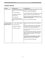
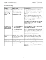
Page 23: ...ire insulation If properly connected and no spark replace igniter E Clean or replace the pilot assembly 2 Pilot will not stay lit after carefully following lighting instructions A Low or too high gas...

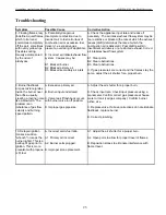
Page 24: ...orifice clean or replace Note do not use any metal cleaning device as this may damage the orifice 4 Pilot and burner come on but go out after some warm up A Inconsistent or insufficient flame on therm...

Page 25: ...2 Clear obstructions B3 Clear obstructions C If gas pressures are correct and the flames stay the same adjust the air shutter for a proper burn 9 Burner flashback Air gas mixture ignites inside the bu...

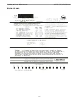
Page 26: ...ir intake system is disassem b led for any reason r einstall per the instru ctions provided with the initial instructions This ven ted gas fi replace heater is not for use witha ir filte rs This appli...

Page 27: ...third 3rd anniversary of the Purchase Date 5 year limited warranty Hearthstone warrants the following parts of the Stove against the following occurrences that result from defects in material or work...

Page 28: ...TATES DO NOT ALLOW LIMITATIONS ON HOW LONG AN IMPLIED WARRANTY LASTS SO THE ABOVE LIMITATION MAY NOT APPLY TO YOU THE WARRANTIES CONTAINED IN THIS DOCUMENT EXTEND ONLY TO THE ORIGINAL PURCHASER OF THE...

Page 29: ...29 NOTES...

Page 30: ...30 NOTES...

Page 31: ...31 NOTES...

Page 32: ...lt for front door 1 Once the door is removed place it carefully aside you now have access to the glass frame 2 Remove the 12 mounting screws see figure 17 that attach the frame and glass to the firebo...

Reviews: