


HearthStone
Quality Home Heating Products
MODEL Sterling “G” Direct-Vent
18
Connections
Electrical Connections
T
HERMOSTAT
The Sterling requires a wall-mounted thermostat for operation. The thermostat controls the unit by "calling for
heat" and turning the unit on when the room is cold, and turning the unit off once the room has warmed sufficiently to
satisfy the thermostat.
The Sterling thermostat is controlled by a 750 millivolt DC two-wire circuit. Both the thermostat and 40 feet
of thermostat wire are included with the Sterling as standard equipment.
T
HERMOSTAT
P
LACEMENT
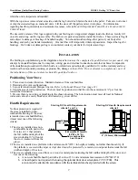
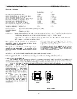
The thermostat should be placed in the same room or living space as the Sterling, typically 5' (1.5 m) off the
floor and away from areas of draft, direct sunlight or other influences which would cause the temperature in the
vicinity of the thermostat to be unrepresentative of the room temperature in general. Such influences might include
strong lighting, a heater vent from the central heating system, a nearby drafty window, etc.
Placement of the thermostat on an inside wall rather than an outside wall is generally preferable. Do not place
the thermostat directly behind or too near the Sterling, otherwise every time the thermostat calls for heat and the unit
turns on, heat from the unit will immediately satisfy the thermostat and turn the unit off.
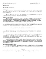
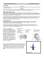
Note
Remove metal facade under ash lip for electrical and gas connections.
T
HERMOSTAT
W
IRING
The thermostat should be connected to the Sterling using 18-gauge insulated thermostat wire supplied. The
thermostat wire from the Sterling to the thermostat can be surface mounted or routed under the floor, through walls,
etc.
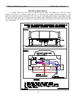
Connect one of the two conductor thermostat wires to the terminal on the gas valve marked "TH".Connect the
other to the yellow wire from the on/off T-stat switch assembly. When making these connections, position the
thermostat wire so that it extends towards the wall behind the Sterling, then towards the thermostat. Check to ensure
that the connections are secure and permanent.
At the thermostat, the thermostat wire should be connected to the two connection screws on the thermostat
base plate per the instructions received with the thermostat. Take care not to over-tighten the connection screws and
not to damage the internal parts of the thermostat. The thermostat should be mounted level for proper operation and
accurate temperature control.
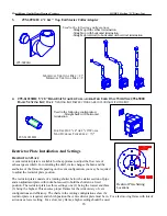
D
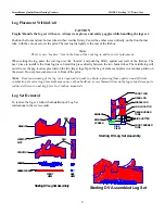
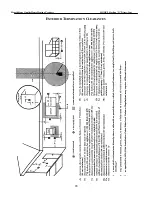
ELAYED IGNITION SAFETY SWITCH
The delayed ignition safety switch should be checked prior to lighting the stove. The rod should be in
the two notches on the top heat exchanger. The bottom of the rod should go through both holes in the switch
bracket.
W
ARNING
Do not attempt to defeat or override this safety switch. Tampering with it by any untrained person is dangerous and
will void the warranty. If there is a delayed ignition, the switch must be reset by a qualified gas technician.


