background image

Hearthstone


Quality 

Home 

Heating 

Products , 

Inc. 

                  ODEL 

8521 

Sterling 

“G” 

B-Vent 


18 

O

PTIONAL 

B

LOWER 

F

AN


An optional blower fan 

(Item #95-57010

) is 

available from the dealer or manufacturer to boost 

heat output efficiency and improve air circulation 

within the room.  It will come with complete 

installation instructions.  The blower fan, which is 

powered by standard 110/115 volt, 60 cycle, 1.6 

amp household current, is easily placed beneath the 

lower rear casting of the unit.  The blower fan has a 

thermo-switch. When the stove heats up, the blower 

fan turns on.  The blower fan will continue to operate 

for a period of time after the unit shuts off as it takes 

some time for the stove to cool down. 


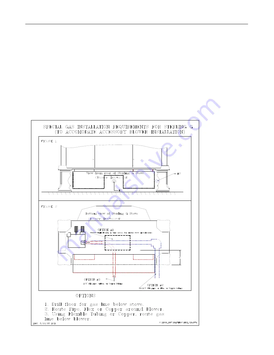
Gas Requirements For Blower 


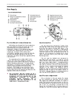
     The gas supply line connection is made to the 

Sterling’s gas control valve using ad" male NPT 

fitting.  The supply line should be ½" diameter pipe 

or tubing.  We recommend a flexible line to avoid 

undue mechanical load on the valve and to ease 

thread alignment.  Check local codes. 


     The unit must be installed and connected in 

accordance with local codes, or, in the absence of 

local codes, with the most current edition of the 

National Fuel Gas Code ANSI Z223.1  CAN/CGA 

B149 Vented Gas Fireplaces Heaters, and 

CAN/CGA 2.17.

  The supply line must include a 

manual shut-off valve and union so that the unit can 

be disconnected for 

servicing.  The gas 

control valve has 

build in pressure 

taps for test gauge 

connections. 


Summary of Contents for STERLING "G" B-VENT 8521

Page 1: ...Installation and service must be performed by a qualified installer service agency or the gas supplier AVERTISSEMENT ASSUREZ VOUS DE BIEN SUIVRE LES INSTRUCTIONS DONNÉ DANS CETTE NOTICE POUR RÉDUIRE AU MINIMUM LE RISQUE D INCENDIE OU POUR ÉVITER TOUT DOMMAGE MATÉERIEL TOUTE BLESSURE OU LA MORT Ne pas entresposer ni utiliser d essence ni autrevaperurs ou liquides inflammables dans le voisinage de c...

Page 2: ...Hearthstone Quality Home Heating Products Inc ODEL 8521 Sterling G B Vent 1 Intentionally Blank ...

Page 3: ...TO COMBUSTIBLES 6 ELECTRICAL CONNECTIONS 7 VENTING CHIMNEY REQUIREMENTS 8 Gas Supply 9 Log Placement Within Unit 11 Lighting the Unit for the First Time 11 Lighting the Unit for the First Time 12 Initial adjustments 14 Daily Operation 16 Routine Maintenance and Care 17 Optional Blower Fan 18 Gas Requirements For Blower 18 Trouble Shooting 19 Parts List 20 Specifications 21 Safety Label 22 Electric...

Page 4: ...ch will complement any room even when it is not burning However when your Sterling is burning it provides the warmth of radiant heat from the granite marble and soapstone tiles Your Sterling is easy to use too There is no chopping hauling or stacking wood simply adjust the temperature on your wall mounted thermostat and it will keep your home at a comfortable temperature throughout the year Welcom...

Page 5: ...ssary Keep your original receipt in a safe place as proof of purchase Serial Number Fuel type Natural Gas Liquid Propane Sold by Date of Purchase Address Phone E mail Website Installed by Date of Installation Address Phone E mail Website Gas Supplier Address Phone E mail Website Read this Owner s Manual before installing or operating your Sterling Retain this manual for future reference SERVICE RE...

Page 6: ... objects that may obstruct air circulation on under or near this heater Clearances to combustibles must be maintained as specified elsewhere in this manual The Sterling should be located out of traffic and away from furniture draperies clothing and flammable material Children and adults who are unfamiliar with heaters of this type should be alerted to the hazards of high surface temperatures and w...

Page 7: ...sfy these requirements However extremely air tight structures may require the introduction of supplemental air from the outside to allow for the proper operation of the unit CAUTION ANY SHIELD DOOR SAFETY SCREEN OR COMPONENT REMOVED FOR SERVICING THE STERLING MUST BE REPLACED PRIOR TO OPERATING THE UNIT IF YOU BELIEVE THAT YOUR STERLING IS NOT PERFORMING PROPERLY IN ANY WAY WHATSOEVER IMMEDIATELY ...

Page 8: ...SET Prior to removing the shipping crate inspect the crate for visible signs of damage Carefully remove the shipping crate Carefully remove and set aside the three top stones NOTE The three top stones are not cemented or otherwise permanently fastened in place Use the protective wrapping to protect them from damage while the unit is inspected and installed Inspect the Sterling for visible or conce...

Page 9: ...Hearth Requirements Floor Protection Clearances to Combustibles Electrical Connections Thermostat Venting Chimney Requirements Gas Supply Log Placement Within Unit Hearth Requirements The floor protection must meet one of the following criteria 1 A non combustible hearth pad with an R value of 1 1 and a minimum measurement of 30 W x 16 D The hearth pad must extend 16 in front of the stove measured...

Page 10: ...rizontal through the wall vent Vertical Exit Installations Using Single Wall Stovepipe Parallel Setting 6 152 mm rear wall to stovepipe Figure 1 4 side wall to stove Corner Setting 3 75 mm rear wall to stove Figure 2 Vertical Exit Installation Using Type B 1 Vent Parallel Setting 2 51 mm rear wall to stove Figure 1 4 side wall to stove Corner Setting 3 75 mm rear wall to stove Figure 2 Horizontal ...

Page 11: ...rable Do not place the thermostat directly behind or too near the Sterling otherwise every time the thermostat calls for heat and the unit turns on heat from the unit will immediately satisfy the thermostat and turn the unit off NOTE Remove facade under ash lip for electrical and gas connections Thermostat Wiring The thermostat should be connected to the Sterling using 18 gauge insulated thermosta...

Page 12: ...idered to be exposed to the outdoors Four inch flexible pipe can be used in place of Type B 1 vent pipe wherever it is impractical or impossible to install rigid Type B 1 vent pipe However flexible pipe is less desirable than B 1 vent pipe because there is a greater heat loss along the length of flex pipe which may result in a reduced or unacceptable draft Draft Hood Down Draft Sensor Spill Switch...

Page 13: ...requirement of the CAN CGA 2 17 Installation Codes Gas Connection The gas supply line connection is made to the Sterling s gas control valve just inside the right rear leg of the unit using a d male NPT fitting The supply line should be diameter or appropriately sized to provide a sufficient gas supply to meet the maximum demand of the unit without undue loss of pressure We recommend a flexible li...

Page 14: ...individual shutoff valve must be disconnected from the gas supply piping system during any pressure testing of that system at test pressures in excess of psig The Sterling must be isolated from the gas supply piping system by closing its individual manual shutoff valve during any pressure testing of the gas supply piping system at test pressures equal to or less than psig 3 M IN C ap N ipple ToE q...

Page 15: ...g will now fit over the post locators provided on the two larger logs Open the bag of embers and place in a single file row across the front burner tube on top of the screen Do not place embers on or in front of the pilot Spread the Platinum Bright Embers randomly over the logs NOTE Exact positioning of the log set is required in order to obtain a pleasing flame pattern and efficient combustion In...

Page 16: ...h no time restrictions on the length of burn PILOT LIGHT WARNING The Sterling has a piezoelectric spark igniter the push button located just above the gas control valve behind the valve access door which ignites the pilot light by means of a spark at the pilot light assembly Do not attempt to light the unit with a match or by any means other than the piezoelectric spark INSTRUCTIONS PRIOR TO FIRST...

Page 17: ... Turn off all electric power to the appliance if service is to be performed Unplug accessory fan if equipped 3 If shutting the unit for the non heating season turn gas control knob fully clockwise to OFF Do not force As a supplement to the above instructions When pressing clicking the piezoelectric spark ignition button to light the pilot light watch through the glass front door of the unit Click ...

Page 18: ... pattern to stabilize There are two simple guidelines to aid in determining the correct flame pattern 1 If the flame at the base of the logs is completely blue the air shutters may be open too far 2 If the flame is dirty or licks the top of the stove the air shutters may be closed too far To adjust the air shutter openings simply loosen the screw on the shutter clamp and pull the adjustment rod to...

Page 19: ...t but not so large as to create excessive noise or consume excessive gas However it can be adjusted by means of the pilot light adjustment screw located on the gas control valve Remove the front lower facade to access Note too that the pilot light flame must properly engulf the thermopile so that the thermopile can generate sufficient milli voltage 750mv to power the millivolt gas control valve Co...

Page 20: ...n select the optimum flame size for their setting and application During the summer non heating season switch the wall thermostat to OFF and turn off the pilot This will improve the overall efficiency of the unit as the heat from the pilot is wasted When putting the unit back into service follow the lighting instructions described elsewhere in this manual When the unit first lights especially when...

Page 21: ...ogs out of the firebox fasten the door shut and momentarily light the unit according to the lighting instructions described elsewhere in this manual Check to ensure that a flame is burning from each burner port The pilot light flame should be large enough to engulf the sensor thermocouple as described elsewhere in this manual Initial Adjustments Pilot Adjustment Turn the unit off by setting the th...

Page 22: ...me after the unit shuts off as it takes some time for the stove to cool down Gas Requirements For Blower The gas supply line connection is made to the Sterling s gas control valve using ad male NPT fitting The supply line should be diameter pipe or tubing We recommend a flexible line to avoid undue mechanical load on the valve and to ease thread alignment Check local codes The unit must be install...

Page 23: ... for proper inlet pressure for the gas being used B1 Check pilot flame to see that it is impinging on the top 9 5 mm of the thermocouple Clean and or adjust pilot for maximum flame impingement B2 Ensure that the thermocouple connection at the gas valve is tight and thermocouple is fully inserted into the pilot bracket and is tight Hand tight plus turn B3 Check thermocouple output using milli volt ...

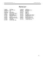
Page 24: ...e Size 55 7211 503 Middle Log 7200 129 Burner Orifice Size 44 7211 504 Front Log 7211 505 Bag of Embers 7211 212 Front Burner Tube Lower 7211 310 Gas Valve Sit NG 7211 202 Rear Burner Tube Upper 7211 372 Pilot Burner Assy NG 7211 026 Spillage Switch 94 58405 Glass Kit 95 56211 LP Fuel Conversion Kit 7211 430 Piezo ceramic and wire 95 56210 NG Fuel Conversion Kit 7210 103 Piezo push button igniter ...

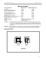
Page 25: ...ize Flue exit 4 diameter top or rear exit reversible Chimney requirement Type B 1 vent 4 diameter Ignition Standing pilot light Certification Tested to ANSI Z 21 88 2002 CSA 2 33 M02 Vented Gas Fireplace Heaters and CAN CGA 2 17 M91 high altitude Approved for use in the state of Massachusetts by The Commonwealth of Massachusetts Board of State Examiners of Plumbers and Gas Fitters Installation Ins...

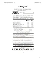
Page 26: ... LP MINIMUM CLEARANCES TO COMBUSTIBLE CONSTRUCTION REAR OF STOVE TO BACK WALL EDGE OF TOP CASTING TO SIDEWALL EDGE OF TOP CASTING TO DIAGONAL WALL UNIT TOP TO ALCOVE CEILING 2 50 mm 4 100 mm 3 75 mm 14 355 mm BLOWER ASSEMBLY Part number 95 57010 168 CFM MAY BE USED ELECTRICAL RATING 115 VOLTS 2 4 AMPS 60 HZ UL CSA LISTED DANGER RISK OF ELECTRICAL SHOCK DISCONNECT POWER BEFORE SERVICING UNIT DO NOT...

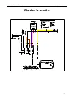
Page 27: ...Quality Home Heating Products Inc ODEL 8521 Sterling G B Vent 23 Electrical Schematics HearthStone Bk B Bk Y Br B Bk Y V Bk Bk G YG R c 50 70 90 10 20 30 O OFF 50 60 70 80 90 c 10 20 30 O Bk V Bk W Wiring Color KEY ...

Page 28: ...Hearthstone Quality Home Heating Products Inc ODEL 8521 Sterling G B Vent 24 OPTIONAL BLOWER ...

Page 29: ...ion or safety of the Stove III Glass against breakage due to thermal shock LIMITED FIVE YEAR WARRANTY Hearthstone warrants the following parts of the Stove against the following occurrences that result from defects in material and workmanship Firebox and firebox baffle against breakage cracking or burn through Convective heat exchanger against breakage cracking or burn through Burners air shutters...

Page 30: ... time VIII Damage operational related problems or inadequate performance caused by site installation or environmental conditions beyond Hearthstone s control including but not limited to nearby trees rooftops buildings wind hills mountains inadequate or excessive venting insufficient make up air or negative air pressure whether or not caused by mechanical systems such as furnaces exhaust fans clot...

Page 31: ...er to make a service call Hearthstone or a Dealer as the case may be will request that the Original Owner return the defective part or the entire Stove if needed with shipping prepaid to Hearthstone or a Dealer Notwithstanding any other provision of this document the Original Purchaser shall pay for any travel fees and service charges related to a Dealer s service call Parts Hearthstone will repla...

Page 32: ...ed and signed Warranty Registration Form which is enclosed in the Stove warranty packet to the following address Hearthstone Quality Home Heating Products Inc Warranty Department 317 Stafford Avenue Morrisville VT 05661 NOTE SENDING IN THE SIGNED WARRANTY REGISTRATION FORM IS NOT A CONDITION OF WARRANTY COVERAGE OR HEARTHSTONE S PERFORMANCE ...

Reviews: