background image

HearthStone Quality Home Heating Products Inc


STERLING Ht Gas-Fired Direct Vent heater                                        

L

IGHTING THE 

U

NIT THE 

F

IRST 

T

IME 


CAUTION:   Lighting th e Sterling-Ht for the 

first time and adjustments to the unit should 

be  performed only by quali

fied  service 

personnel. 


S

MOKE AND 

F

UMES 

W

ARNING


When lit for the first time, the Sterling will emit some 

smoke  and fumes.  This is norm al  “off-gassing”  of 

the  paints an d  oils  used  in  the m anufacturing  and 

assembly  of  the  unit.  Open windows to vent the


room  if nec essary.  The off gassing and fum es  will 

subside after the first 10 to 20 minutes of operation. 


O

DORS AND 

I

MPURITIES


A  heater of this t ype  may  produce  odors d uring 

heater  operation  due to im purities  that  may  exist in 

the  immediate  area.    Sources  of i mpurities  can  be 

cleaning  solvents, paint s olvents,  cigarettes, s moke, 

soot  from  scented  candles, pet hair,  dust,  adhesives, 

new carpet, and/or textiles.  Such odors will dissipate.  

However, opening a wind ow or otherwise providin g 

additional  ventilation  to  the  area can alleviate th e 

condition.  If any odor persists, contact your dealer or 

an authorized service technician. 


P

ILOT 

L

IGHT


The  Sterling has a batte ry  operated  electric  spark 

igniter,  which  ignites the pilot   light  by m eans  of a 

spark  at the   pilot light  assembly.  To activate the  

igniter, turn the gas control knob to ‘Pilot’ and push 

and  hold  it  down.  You  must  install the included  

battery  for the igniter. The battery   compartment  is 

located  in the lower rear  area  of the s tove.  Do not 

attempt  to light t he  unit  with a m atch  or by any 

means other than the electric spark. 


P

REPARE FOR 

L

IGHTING


Prepare  for the lighting procedure by   adjusting  the 

thermostat to its lowest setting or OFF position. If the 

gas control knob is not in the OFF position, turn the  

knob  fully  clockwise  to  OFF.   Locate the variabl e 

output  control  knob  and  turn it f ully  counter-

clockwise to the highest setting. 


I

NITIAL 

A

DJUSTMENTS


Once  the Sterling-Ht is set in place, connected and 

assembled as described in the Asse mbly of the Unit, 

Electrical  Connections,  and Gas Suppl

y  & 

Connections sections of this manual, the unit is ready 

to be lit for the first time.  Each unit is  tested prior to 

shipment by the manufacturer, so ignition should take 

place  without  failure.    However,  a  number  of  small 

adjustments  may  be necessary   to com pensate  for 

variations in gas pressure, altitude, and other factors  

particular to each installation. 


Prior  to light ing  the unit  for  the first time, wait 5  

minutes to allow any residual gas within the unit t o 

dissipate.  Smell all around the appliance area for gas.  

Be sure to smell next to the floor because some gases 

(LP) are heavier than air  and will settle on the floor.  

If you do not smell gas  after this five-minute period , 

proceed with the lighting procedure.  

If you do smell 

gas,  do  not  proceed  with  the lighting procedure.   

Instead,  immediately  refer  to th e  What  to  Do  If 

You  Smell Gas Warnin g,  on the c over  of this 

manual. 


L

IGHTING 

I

NSTRUCTIONS


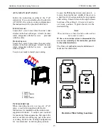
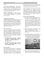
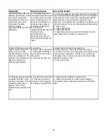
The gas control knobs are located at the top, right 

rear corner of the unit (

see diagram on next page

). 


1.  Set the on/off/T-stat switch or thermostat to the 

off position. 

2.  Unplug the blower accessory, if so equipped 

3.  Push in and turn gas control knob clockwise to 

“OFF

”. 

 (If not previously lit, the knob should be 

in this position.)


4

Wait (5) five minutes to clear out any gas.  If you 

then smell gas, STOP! 

Smell all around the 

appliance area for gas. Be sure to smell next to 
the floor because some gases (LPG) are heavier 
than air and will settle on the floor. If you smell 
gas immediately follow the What To Do If You 
Smell Gas! warning on the cover of this Manual.


If you do not smell gas, go to the next step. 

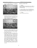
5.  Turn gas control knob counterclockwise to 

“PILOT”. 

6.  Push in control knob all the way and hold in. 

(You should hear the clicking of the igniter in the 

firebox) Verify ignition of the pilot. Continue to 

hold the control knob in for about 20 seconds 

after the pilot is lit (ensures thermocouple is up to 

temperature).  Release the knob and it will pop 

back out. Pilot should remain lit.  If the pilot goes 

out, repeat the operation. 


If knob does not pop o ut when released, stop 

and  immediately  call a qualified service 

technician or gas supplier. 


If the pilot will not stay lit after several tries, 

turn the gas control knob “OFF” and call a 

qualified service technician or gas supplier. 

19  

Summary of Contents for Sterling-Ht 8532

Page 1: ... agency or gas supplier must perform installation and service In the Commonwealth of Massachusetts all installation of gas lines and gas fitting shall only be done by a licensed gas fitter or licensed plumber AVERTISSEMENT Assurez vous de bien suivre les instructions donné dans cette notice pour réduire au minimum le risque d incendie ou pour éviter tout dommage matéeriel toute blessure ou la mort...

Page 2: ...s and warranty claims if nece ssary Keep your original receipt in a saf e place as proof of purchase Serial Number Fuel type check one Natural Gas Liquid Propane Sold by Phone Date of Purchase Installed by Phone Date of Installation Gas Supplier Phone Read this Owner s Manual before installing or operating the STERLING heater Retain this manual for future reference SERVICE RECORD Date Who Performe...

Page 3: ...AND MAINTAINED BY QUALIFIED SERVICE PERSONNEL Verify the gas connections and venting systems with requirements of local regional or natio nal installation codes Qualified service personnel must inspect the gas heater before use and at least annually ALWAYS VENT TO THE OUTSIDE Never vent the gas heater to other rooms or buildings Do not con nect this gas appliance to a chimney flue serving a s epar...

Page 4: ...tion Clearances to combustibles must be maintained as specified in the Clearances To Co mbustibles section of this manual Due to high tem peratures the appliance should be located out of traffic an d away from furniture draperies clothing and other flammable materi als Children and adults should be al erted to the hazards of high surface temperatures and must stay away to avoid burns to skin or po...

Page 5: ...nds after the pilot is lit Release the knob and it will pop back out Pilot should remain lit If the pilot goes out repeat the operation If knob does not pop out when released stop and immediately call a qualified service technician or gas supplier If the pilot will not stay lit after several tries turn the gas control knob OFF and call a qualified service technician or gas supplier 7 Turn gas cont...

Page 6: ...ct for Damage The Sterling is packaged by the m anufacturer to withstand normal shipment without dam age However damage can still occur during transit so take care to inspect for damage when unpacking and installing the unit If any damage or a missing part is detected immediately contact y our dealer Do not install or put into service a damaged or incomplete heater The unit should appear to be squ...

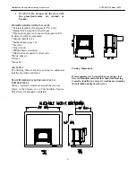
Page 7: ... wrench Phillips head screwdriver Other parts as required by local code Safety Glasses Gloves Stone Set AIR SUPPLY The Sterling Direct vent does not requi re additional installer provided ventilation STOVE DIMENSIONS CLEARANCES TO COMBUSTIBLES Always maintain clearances around the stove as shown in the Clearan ces to Com bustibles figures This allows for adequate ventilation Sterling Dimensions If...

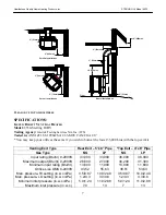
Page 8: ...fices the same if you wish to burn at the lower 33 000 btus with the top exit kit Venting Exit Type Rear Exit 5 x8 Pipe Top Exit 4 x6 Pipe Gas Type NG LP NG LP Input rating Btu hr 0 2000ft 33 000 33 000 38 000 38 000 Maximum output Btu hr 0 2000ft 26 600 27 400 30 200 31 300 Minimum input rating Btu hr 13 600 11 900 13 900 11 600 Orifice size DMS 0 2000ft 43 52 55 63 38 51 53 63 Man pressure HI se...

Page 9: ...Hearthstone Quality Home Heating Products Inc STERLING Ht Model 8532 8 ...

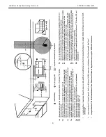
Page 10: ...ent Cap Snorkel 36 Vinyl Siding Standoff 4 x 6 5 8 Round Ceiling Support Wall Thimble Covers Wall thimble If the vent air intake s ystem for any reason is disassembled it m ust be reinstalled per the instructions provided for in the initial installation Allowable Venting Configuration Graphs When determining the venting configuration you must consider the position of the termination cap There are ...

Page 11: ...himney Installation The use of an existing chimney as an air intake is not covered under the ANSI Z21 88 1998 CSA 2 33 M98 test methods and the resulting ITS WHI product certification The Code Authority Having Jurisdiction must be consulted prior to proceeding with this installation method 10 ...

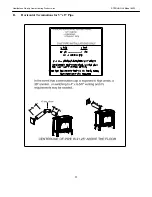
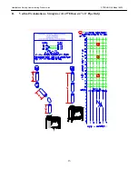
Page 12: ...Hearthstone Quality Home Heating Products Inc STERLING Ht Model 8532 B Horizontal Terminations for 5 x 8 Pipe 11 ...

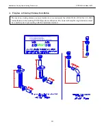
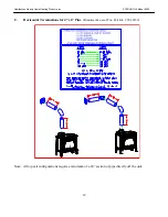
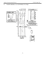
Page 13: ...Heating Products Inc STERLING Ht Model 8532 12 C Horizontal Terminations for 4 x 6 Pipe Requires the use of Top Exit Kit 95 60320 Note All top exit configurations require a minimum of a 24 section of pipe directly off the unit ...

Page 14: ...Hearthstone Quality Home Heating Products Inc STERLING Ht Model 8532 D Vertical Terminations Straight or 2 45O Elbows 4 x 6 Pipe Only 13 ...

Page 15: ...Hearthstone Quality Home Heating Products Inc STERLING Ht Model 8532 E Vertical Terminations 1 or 2 90O Elbows 4 x 6 Pipe 14 ...

Page 16: ...t to a top exit 4 x6 pipe a restrictor is supplied with the kit supplied with our restrictor e middle of the stove to position which corresponds to the ap propriate roximate locations of the settings 1 3 however it can be set in any position Ti ghten the screw in the desired setting Note These positions are based on lab results and can have some variance IF the vent air intake system is disassembl...

Page 17: ... which have holes in the side for acce ssing Do not remove these screws just loosen them Slide the side cover upward and remove The gas suppl y line connection is made to the Sterling s gas control valve located on the back of the unit in the lower right corner using a 3 8 NPT fitting The pipe must be sized to provide sufficient gas supply to meet the maximum demand of the unit The supply line mus...

Page 18: ...it in the firebox This log set is specifically designed to work with the provided em ber burner Do not use any other type of fiber logs wood logs or other materials in the firebox If the original log set is damaged or broken contact yo ur Hearthstone dealer for replacement The decorative fiber log s et will last a long tim e however they will break easily if subjected to rough or improper handling...

Page 19: ...he fire box Slide t he lower portion of the glass as sembly into the slots and push it flush against the firebox Rotate the clips into the locked position Re install the front cast by sliding the upper portion under the lip of the top and t ilting the bottom in flush with the glass assembly It should then slide downward and be snug in place Make sure t he glass assembly is properly secured to the ...

Page 20: ...ions sections of this manual the unit is ready to be lit for the first time Each unit is tested prior to shipment by the manufacturer so ignition should take place without failure However a number of small adjustments may be necessary to com pensate for variations in gas pressure altitude and other factors particular to each installation Prior to light ing the unit for the first time wait 5 minute...

Page 21: ...fected by a combination of heat output and the thermostat setting If your stove turns on and off too often try first reducing the burn cycle by turning the HI LOW knob on t he control valv e to a lower setting Using the variable output con trol the heat output of the unit can be reduced for mild fall and spring months or m aximized for the colder winter months This adjustm ent can be made by the h...

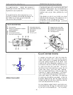
Page 22: ...g off all gas flow the pilot burner cannot be relit until the thermocouple has cooled allowing th e electromagnet to be released Approx 60 sec The gas control knob is designed to operate by hand Do not use any tools during this operation GAS CONVERSIONS All Sterling stoves are set up for use with Natural Gas when built However these uni ts are easily converted for use with LP and visa versa Th e i...

Page 23: ...et Take care to thorou ghly vacuum the ports holes on the top of t he ember burner With the decorative fiber logs o ut of the fir ebox re install the glass assembly and briefly light the unit according to lighting instructions described on Page 4 Check to ensure a flame is burnin g from each burner port Check the pilot The pil ot flame should be large enough to en gulf the t hermocouple and therm ...

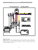
Page 24: ...ram Sterling Ht DV Wiring Color KEY WIRING INSTRUCTIONS Caution Label all wires prior to disconnection when servi cing controls Wiring errors can cause improper and dangerous operation Verify proper operation a fter servicing Attention Au moment de l entretien des commandes étiquetez tous les fils avant le débranchement Des erreurs de câblage peuvent entraîun fonctionnement inadéquat et dangereux ...

Page 25: ...ATTERY IGINTOR BOX 0373 801 7210 105 IGNITOR SWITCH BATTERY OPER 5532 010 STG DV FIREBOX 7211 054 GAS MANIFOLD 5532 014 PILOT SHIELD 7211 136 ORIFICE PILOT LP 35mm CONVERT TOP 5532 015 INLET PLENUM 7211 214 AIR SHUTTER 5532 017 ORIFICE MOUNTING PLATE 7211 215 FIBER EMBER BURNER 5532 020 EXHAUST HEAT EXCHANGER 7211 216 BURNER INLET TUBE 5532 025 REAR TOP HEAT SHIELD 7211 316 GAS VALVE HIGH TURNDOWN...

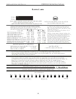
Page 26: ...rohibited by local codes See owner s manual for details This appliance is not convertible for use with other gases unless a certified kit is used If the vent air intake system is disassembled for any reason reinstall per the instructions provided with the initial instructions This vented gas fireplace heater is not for use with air filters This appliance must be properly connected to a venting sys...

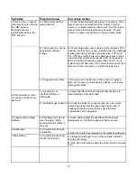
Page 27: ...g for off season summer pilot assembly may be dirty E Clean or replace the pilot assembly 2 Pilot will not stay lit after carefully following lighting instructions A Low or too high gas pressure A Check for proper inlet pressure for the gas being used B Faulty connections B Measure voltage between valve body and solder connection on the rear of the valve where the blue wire connects It should be n...

Page 28: ...ner does not come on replace the gas valve C Plugged burner orifice C Remove and check burner orifice clean or replace Note do not use any metal cleaning device as this may damage the orifice 4 Pilot and burner come on but go out after some warm up A Inconsistent of insufficient flame on thermopile A Adjust pilot flame size and assure that the flame is aimed directly at the thermopile B Insufficie...

Page 29: ...If gas pressures are correct and the flames stay the same adjust the air shutter for a proper burn 9 Burner flashback Air gas mixture ignites inside the burner near the orifice usually creating a roaring noise like a blowtorch The problem is an imbalance of gas flow velocity and burning speed pattern A Excessive B Burner input underrated C Valve leak if flashback occurs with burner valve in off po...

Page 30: ...Form which is enclosed in the Stove warranty packet to the following address Hearthstone Quality Home Heating Products Inc Warranty Department 317 Stafford Avenue Morrisville VT 05661 8695 NOTE SENDING IN T HE SIGNED WARRANTY REGISTRATION FORM IS NOT A CONDITION OF WARRANTY COVERAGE OR HEARTHSTONE S PERFORMANCE ...

Reviews: