background image

HearthStone Quality Home Heating Products Inc


STOWE Gas-Fired Direct Vent heater


31

A

IR 

S

HUTTER 

A

DJUSTMENTS


The air shutter is adjustable while the stove 
is burning. Loosen the adjusting nut located 
on the lower right hand corner of the right 
side of the stove while the stove is cool. 
After loosening the nut, light the stove and 
allow the stove to heat to normal 
temperature. Loosen the slider set screw, 
make adjustment and tighten screw. 
 
Moving the slider toward the front of the 
stove increases the air and moving the slider 
toward the back of the stove decreases the 
air. Let the stove cool and tighten the nut. 
The air shutter is factory set and only a 
qualified gas technician should make 
adjustments. 


¦  

W

ARNING

The control has an antilock 

device. After shutting off the gas flow, 
the pilot burner cannot be relit until the 
thermocouple has cooled, allowing the 
electromagnet to be released (approx. 60 
sec.). The gas control knob is designed 
to be operated by hand. Never use any 
tools during this operation. If the knob 
will not push in or turn by hand, don’t 
try to repair it. Call a qualified service 
technician. Damaged knobs may result 
in fire, explosion, or serious injury.


P

ILOT 

A

DJUSTMENT


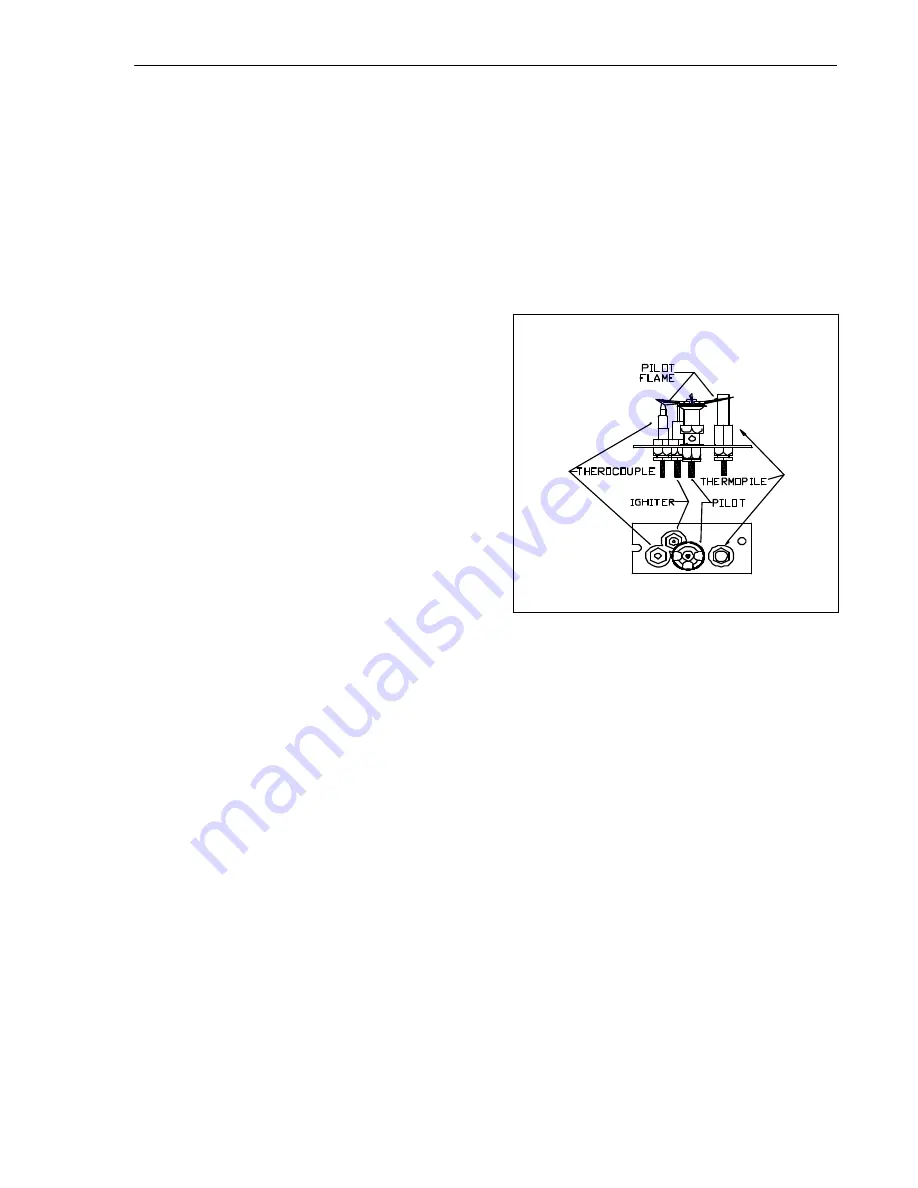
The pilot light is preset by the manufacturer 
and should not need adjustment.  The pilot 
light flame should be large enough to engulf 
the thermopile  and thermocouple located 
next to the pilot, but not so large as to create 
excessive noise or consume excessive gas. 

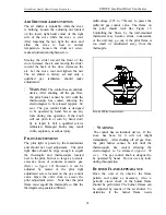
(Refer to figure 12) 

However, it can be 

adjusted by means of the pilot light 
adjustment screw located on the gas control 
valve. Open the valve door to access the 
pilot adjustment screw.  Note that the pilot 
flame must engulf the thermopile so that the 
thermopile can generate sufficient  

milli-voltage (325 to 750-mv) to power the 
milli-volt gas control valve. The flame on 
the pilot should look  like Figure 12. 
Controlling the Stowe by the wall-mounted 
thermostat may become erratic, nonexistent, 
or the unit may go out, if the pilot flame is 
too small or misdirected away from the 
thermopile.


F

IGURE 

12 P

ILOT 

A

DJUSTMENT


¦  

W

ARNING


The control has an interlock device.  If the 

stove has been lit, it will not relight 
immediately.  After shutting off all gas flow, 
the pilot burner cannot be relit until the 
thermocouple has cooled, allowing the 
electromagnet to be released 

(Approx. 60 

sec.)

.  The gas control knob is designed to 

be operated by hand.  Do not use any tools 
during this operation.   


B

URNER 

F

LAME 

A

PPEARANCE


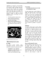
Once the unit is lit, observe the flame 
pattern and adjust as necessary. Also, a 
periodic visual check of the burner flame 
should be performed. The burner flames can 
be adjusted by means of the air shutter. To 
determine if the burner flame needs 

Summary of Contents for Stowe 8320

Page 1: ...e fire department A qualified installer service agency or gas supplier must perform installation and service AVERTISSEMENT Assurez vous de bien suivre les instructions donn dans cette notice pour r du...

Page 2: ...thStone Quality Home Heating Products Inc STOWE Gas Fired Direct Vent heater 2 HearthStone Quality Home Heating Products 317 Stafford Avenue Morrisville Vermont 05661 E Mail Inquiry HearthStoneStoves...

Page 3: ...arranty claims if necessary Keep your original receipt in a safe place as proof of purchase Serial Number Fuel type check one Natural Gas Liquid Propane Sold by Phone Date of Purchase Installed by Pho...

Page 4: ...nstalled and the On Off Thermostat switch is set to Thermostat the wall mounted thermostat will control the on off cycling of the unit At any time you can override the thermostat with the On Off T STA...

Page 5: ...ls r glements selon les Codes d installation CAN CGA B149 Do not use this appliance if any part has been under water Immediately call a qualified service technician to inspect the heater and to replac...

Page 6: ...on until the unit has been inspected and approved by qualified service personnel Prior to servicing the unit turn the valve control knob clockwise to OFF The unit should be cool prior to servicing and...

Page 7: ...and ember strip SPECIFICATIONS LISTED DIRECT VENT GAS HEATER Listed DV Gas Heater Model Stowe DV Room Heater Testing Agency Intertek Testing Services NA Inc ITS Tested to ANSI Z21 88 1998 CSA 2 33 M9...

Page 8: ...gas immediately follow the What To Do If You Smell Gas warning on the cover of this Manual If you do not smell gas proceed to the next step 5 Set the ON OFF T STAT switch to ON or if the thermostat ha...

Page 9: ...gas fired heater is easily operated by the homeowner once installed and adjusted by a qualified service technician Following is a list of the controls available to the owner user A ON OFF PILOT Built...

Page 10: ...temperature of the stove from anywhere in the vicinity of the unit G BLOWER The unit may be equipped with an OPTIONAL variable blower fan available through your local HearthStone dealer Kit 93 57001...

Page 11: ...should be inspected by qualified service personnel to ensure that it is clean free of obstruction safe and in good working order If service or maintenance is required qualified service personnel shoul...

Page 12: ...he decorative ceramic logs as they are fragile and subject to damage and breakage To open the firebox remove the two upper front screws located in the grill of the front that hold the cast fa ade onto...

Page 13: ...d allow for adequate ventilation Be sure to consider the need for access to the gas control valve access door on the front of the unit as well as full access for periodic cleaning and servicing Also c...

Page 14: ...HearthStone Quality Home Heating Products Inc STOWE Gas Fired Direct Vent heater 14...

Page 15: ...HearthStone Quality Home Heating Products Inc STOWE Gas Fired Direct Vent heater 15 Possible Vent TERMINATION locations...

Page 16: ...8 32 x 3 8 Phillips Head self tapping screws NOTE If required to use the restriction plate please refer to Figure 1 for correct locations of the additional gasket restriction plate and inner adapter...

Page 17: ...o a wall or siding Note If further direction is needed for installation please refer to the venting instructions which are provided with the venting manufacturer s instructions Note A Restrictor Kit 9...

Page 18: ...m height 6 maximum offset refer to Figure 2 12 maximum offset refer to Figure 3 The termination must fall within the outline shown in Figures 2 3 Use the indicated restriction plate position The restr...

Page 19: ...rectly off the heater Use a vinyl siding standoff when installing against vinyl siding Horizontal sections require a rise every 12 of horizontal run NOTES 1 The vent must terminate within one of the r...

Page 20: ...20 APPROVED CONFIGURATION FOR FIREPLACE INSTALLATION The termination must fall within the demarcation line shown in the illustration Use the indicated restriction plate position Restriction plate 595...

Page 21: ...nto the 10 x 10 wall pass through Secure it with 4 screws not provided Install the exterior portion of the thimble in similar fashion overlapping the 2 sections Caution For building with vinyl siding...

Page 22: ...you would like to control the temperature via the remote control use Kit 90 56914 Installation instructions are provided with the kits THERMOSTAT PLACEMENT The thermostat should be placed in the same...

Page 23: ...ependently of the burner flames Installation instructions are provided with the Kit ELECTRICAL GROUNDING INSTRUCTIONS WHEN BLOWER FAN IS INSTALLED This appliance is equipped with a three prong groundi...

Page 24: ...ucts Inc STOWE Gas Fired Direct Vent heater 24 Wiring Diagram Wiring Color KEY Bk V Y Bk Bk Hearthstone c 50 70 90 10 20 30 OFF O YG 50 60 70 80 90 c 10 20 30 O Bk R G Bk Bk W Br Bk W Y Bk V W Bk B W...

Page 25: ...black iron or steel pipe only with a flexible line to the valve and to ease thread alignment but refer to local codes Internally tinned copper tubing can be used in some areas when permitted by local...

Page 26: ...pieds 610 et 1370m seulement See data plate for additional information For high altitude installations consult the local gas distributor or the authority having jurisdiction for proper rating methods...

Page 27: ...ne layer high the 2 ounces of Charcoal Embers 5 You will not need to use all of the Charcoal Embers Keep the rest in to use in the future 6 Make sure the front is properly secured to the firebox befor...

Page 28: ...ufacturing and assembly of the unit Open windows to vent the room if necessary The off gassing and fumes will subside after the first 10 to 20 minutes of operation ODORS AND IMPURITIES A heater of thi...

Page 29: ...ced by the unit by varying the gas pressure to the main burner tube A combination of heat output and the thermostat setting affect the length of the burn cycle If your stove turns on and off too often...

Page 30: ...nnot be corrected through air shutter adjustment an adjustment must be made to the gas supply pressure or by changing the restriction plate location Qualified service personnel must preform supply lin...

Page 31: ...d not need adjustment The pilot light flame should be large enough to engulf the thermopile and thermocouple located next to the pilot but not so large as to create excessive noise or consume excessiv...

Page 32: ...to prevent the buildup of dust and lint The exterior surfaces of the unit can be cleaned using soap water and a soft cloth Do not use abrasive or chemical cleaners and take care not to scratch the gl...

Page 33: ...is kept free and clear from combustible materials gasoline and other flammable vapors and liquids Check that the flow of combustion and ventilation air is not obstructed Once a year the unit and its v...

Page 34: ...11 009 PILOT TUBE 5320 030 HEAT SHIELD SIDE OUTER 7211 018 TUBE GAS FLEX 3 8 x 12 BURNER 5320 031 HEAT SHIELD SIDE INNER 7211 020 BURNER INLET ELBOW 3 8 COMP 5320 032 HEAT SHIELD SIDE SPACER 7210 007...

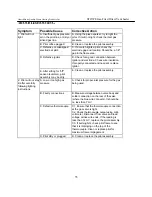
Page 35: ...E After sitting for off season summer pilot assembly may be dirty E Clean or replace the pilot assembly 2 Pilot will not stay lit after carefully following lighting instructions A Low or too high gas...

Page 36: ...the pilot assembly If the meter reading is OK but the burner does not come on replace the gas valve C Plugged burner orifice C Remove and check burner orifice clean or replace Note do not use any meta...

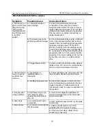
Page 37: ...livery or a restricted exhaust Correct air intake exhaust flow system B Incorrect air intake exhaust flow system Causes may be B1 Blocked Burner B2 Blocked primary air B3 Blocked secondary air inlets...

Page 38: ...hoosh noise as the burner lights This is a buildup of gases prior to ignition This is more prevalent with propane LP fuel A Incorrect air to fuel ratio A1 Primary air incorrect A2 Burner ports plugged...

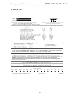
Page 39: ...HearthStone Quality Home Heating Products Inc STOWE Gas Fired Direct Vent heater 39 RATING LABEL...

Page 40: ...ainst the following occurrences that result from defects in material and workmanship Firebox and firebox baffle against breakage cracking or burn through Convective heat exchanger against breakage cra...

Page 41: ...yers etc 9 A defect in any part of the Stove if the Original Purchaser fails to comply with HearthStone s or a Dealer s request to ship the part or the Stove to HearthStone or a Dealer as the case may...

Page 42: ...the foregoing warranties at no charge Labor Within the first 1st year after the Purchase Date HearthStone will pay for warranty labor performed by a Dealer at HearthStone s published labor rates in ef...

Page 43: ...HearthStone Quality Home Heating Products Inc STOWE Gas Fired Direct Vent heater 43...

Reviews: