background image

Hearthstone Quality Home Heating Products, Inc.


STOWE Model 8324


21 


L

IGHTING THE 

U

NIT THE 

F

IRST 

T

IME


S

MOKE AND 

F

UMES 

W

ARNING


When  lit  for  the  first  time,  the  Stowe  will  emit  some 
smoke and odors. This is normal “off-gassing” of the 
paints  and  oils  used  in  the  manufacturing,  and 
assembly  of  the  unit.  Open  windows  to  vent  the 
room  if  necessary.  The  off  gassing  and  fumes  will 
subside after the first 10 to 20 minutes of operation. 

Once  the  Stowe  in  place  and  connected  as 
described previously, the unit is ready to be lit for the 
first  time.  Hearthstone  tests  each  Stowe  before 
shipment,  so  ignition  should  take  place  without 
failure. 

P

ILOT 

L

IGHT


The Stowe has a piezoelectric spark igniter (the red 
or black push button  located next to the gas control 
valve  behind  the  valve  access  door),  which  ignites 
the  pilot  light  by  means  of  a  spark  at  the  pilot  light 
assembly.  Do  not  attempt  to  light  the  unit  with  a 
match  or  by  any  means  other  than  the  piezoelectric 
spark. 

P

ILOT 

A

DJUSTMENT


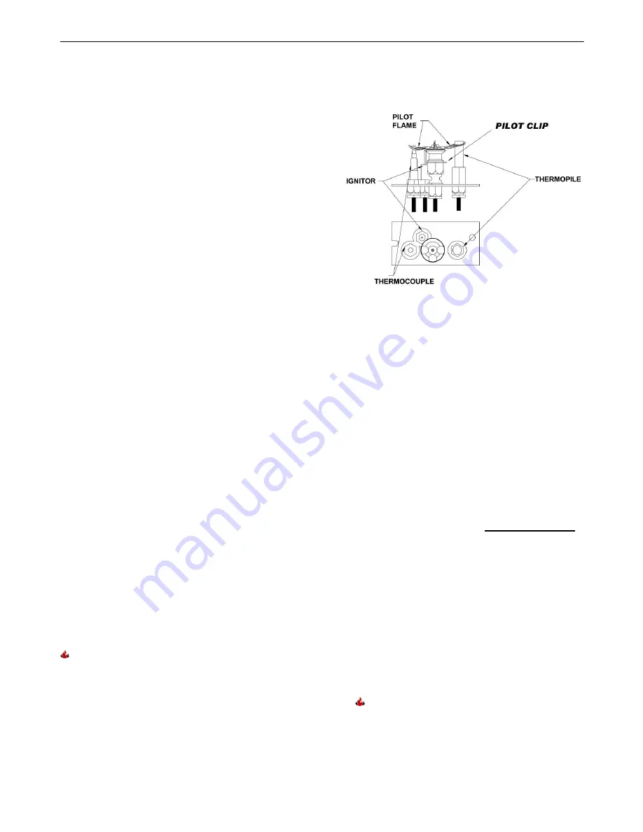
The  pilot  light  is  preset  by  Hearthstone  and  should 
not  need  adjustment.    The  pilot  light  flame  must  be 
large  enough  to  engulf  the  thermopile  and 
thermocouple  located  next  to  the  pilot,  but  not  so 
large  as  to  create  excessive  noise  or  consume 
excessive  gas

However,  it  can  be  adjusted  by 

means of the pilot light adjustment screw located on 
the  gas  control  valve  (

see  Figure  15

).  Remove  the 

ash lip casting to access the pilot adjustment screw.  
Note  that  the  pilot  flame must  engulf  the  thermopile 
so  that  the  thermopile  can  generate  sufficient  milli-
voltage  (325  to  500-mv)  to  power  the  millivolt  gas 
control valve.


Before  lighting,  smell,  or  use  a  gas  detector  all 
around the appliance area to check for gas leaks. Be 
sure  to  test  near  the  floor  because  some  gases 
(LPG)  are  heavier  than  air  and  will  settle  on  the 
floor. If you detect gas, check for leaks.  


WARNING!


THE  CONTROL  HAS  AN  INTERLOCK 

DEVICE.  IF  THE  STOVE  WAS  RECENTLY 
BURNING,  IT  WILL  NOT  RELIGHT  IMMEDIATELY. 
AFTER  SHUTTING  OFF  ALL  GAS  FLOW,  THE 
PILOT  BURNER  WILL  NOT  RELIGHT  UNTIL  THE 
THERMOCOUPLE  HAS  COOLED,  RELEASING 
THE  ELECTROMAGNET 

(APPROX.  60  SEC.)

.  THE 

GAS 

CONTROL 

KNOB 

IS 

DESIGNED 

TO 

OPERATE  BY  HAND.  DO  NOT  USE  ANY  TOOLS 
DURING THIS OPERATION.   


Figure 25: Pilot Assembly Detail 

 
L

IGHTING 

I

NSTRUCTIONS


1.  Set the on/off/T-stat switch or thermostat to the 

off position. 

2.  Unplug the blower accessory, if so equipped. 

3.  Push in and turn gas control knob clockwise to 

“OFF”. 

 (If not previously lit, the knob should be 

in this position.)


4.  Wait (5) five minutes to clear out any gas.  If you 

then smell gas, STOP! 

Smell all around the 

appliance area for gas. Be sure to smell next to 
the floor because some gases (LPG) are heavier 
than air and will settle on the floor. If you smell 
gas immediately, follow the 

What To Do If You 

Smell Gas!

 warning on the cover of this Manual.


If you do not smell gas, go to the next step. 

5.  Turn gas control knob counterclockwise to 

“PILOT”. 

6.  Push in control knob all the way and hold in. 

Immediately light the pilot with the gas lighter 
(push in and “click” the piezoelectric spark 
igniter button several times until lit). Continue to 
hold the control knob in for about 20 seconds 
after the pilot is lit. Release the knob and it will 
pop back out. Pilot should remain lit.  If the pilot 
goes out, repeat the operation. 

  If knob does not pop out when released, 

stop and immediately call a qualified service 
technician or gas supplier. 

Summary of Contents for Stowe 8324

Page 1: ...t perform installation and service of this appliance In the Commonwealth of Massachusetts all installation of gas lines and gas fittings must be performed by a licensed gas fitter or licensed plumber...

Page 2: ...Page 1 of 33 Intentionally Blank...

Page 3: ...pt in a safe place as proof of purchase Serial Number Fuel type Natural Gas Liquid Propane Sold by Date of Purchase Address Phone E mail Website Installed by Date of Installation Address Phone E mail...

Page 4: ...loor Protection 9 Venting Information 10 Venting Connection 10 Approved Systems 11 Minimum Venting 12 Electrical System Information 16 Gas Supply Connections 17 Gas Connections 18 Initial Leak Check 1...

Page 5: ...s 02202 Manufactured and Warranted by Hearthstone Quality Home Heating Products Inc 317 Stafford Ave Morrisville VT 05661 8695 USA www hearthstonestoves com Figure 1 Stowe DV Dimensions Specification...

Page 6: ...nit will remain appealing while providing years of quality performance The installation must conform to local codes or in the absences of local codes the current National Fuel Gas Code ANSI Z223 1 NFP...

Page 7: ...E COMPARTIMENT DES COMMANDES SONT PROPRES VOIR LES INSTRUCTIONS D INSTALLATION ET D UTILISATION QUI ACCOMPAGNENT L APPAREIL Hot Surfaces Certain exposed surfaces of the Stowe will reach high temperatu...

Page 8: ...INSTALLATION PREPARATION CODES Adhere to all local codes or in their absence the latest edition of THE NATIONAL FUEL GAS CODE ANSI Z223 1 NFPA 54 or CAN CGA B149 Installer l appareil selon les codes o...

Page 9: ...still occur during transit Take care to inspect for damage when unpacking and installing the unit DO NOT INSTALL OR PUT INTO SERVICE A DAMAGED OR INCOMPLETE HEATER Remove the shrink wrap and other pa...

Page 10: ...adequate ventilation Minimum clearances to combustibles must be maintained as shown in Figures 5 8 Note The rear clearance to combustibles is determined by either the unit s or the vent pipe s minimum...

Page 11: ...tone Quality Home Heating Products Inc STOWE Model 8324 10 Figure 5 Minimum Wall Clearances Figure 6 Corner Clearances Figure 7 Horizontal Vent Mantle Clearance Figure 8 Snorkel Termination Mantle Cle...

Page 12: ...RNING IN HIGH WIND AREAS AND PARTICULARLY COLD CLIMATES IT MAY BE NECESSARY TO HEAT YOUR VENT SYSTEM WITH THE PILOT PRIOR TO IGNITION OF THE MAIN BURNER IN THESE INSTANCES IT IS RECOMMENDED THAT YOU L...

Page 13: ...88 1999 CSA 2 33 M99 test methods this installation has been tested and approved by Intertek Testing Services with an appropriate test The code authority having jurisdiction must be consulted prior to...

Page 14: ...e wall Ensure both of the retaining straps extend through interior wall thimble Before attaching the vent termination to the outside of the house run a bead of non hardening mastic around its outside...

Page 15: ...CAN We strongly recommend 12 inches particularly where strong winds prevail H Not to be installed within 15 feet 4 5m above a meter regulator assembly within 3 feet 91cm horizontally from the center l...

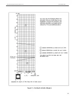
Page 16: ...Hearthstone Quality Home Heating Products Inc STOWE Model 8324 15 Figure 13 Venting Termination Diagram...

Page 17: ...ERRORS CAN CAUSE IMPROPER AND DANGEROUS OPERATION VERIFY PROPER OPERATION AFTER SERVICING ATTENTION AU MOMENT DE L ENTRETIEN DES COMMANDES TIQUETEZ TOUS LES FILS AVANT LE D BRANCHEMENT DES ERREURS DE...

Page 18: ...es equal to or greater than psig Over pressurizing can damage the control resulting in leakage or control malfunction NOTICE A QUALIFIED TECHNICIAN MUST CONNECT THE HEATER TO THE GAS SUPPLY AND LEAK T...

Page 19: ...a fire or explosion GAS CONNECTIONS Connection Main Gas Tubing connections 1 Do NOT use pipe joint compound or Teflon PTFE tape 2 Slip nut and ferrule over tubing 3 Slide nut and ferrule into place a...

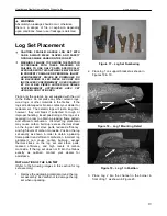
Page 20: ...gs will last a long time however they will break if subjected to rough or improper handling Exact positioning of the log set is required in order to obtain a pleasing flame pattern and efficient combu...

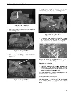
Page 21: ...n 7 Place small tufts of the Platinum Bright Embers on the burner and log surfaces for additional glow as desired do not block burner ports Figure 24 Platinum Bright Embers Enlarged to Show Detail REM...

Page 22: ...l valve Before lighting smell or use a gas detector all around the appliance area to check for gas leaks Be sure to test near the floor because some gases LPG are heavier than air and will settle on t...

Page 23: ...erly adjusted and installed thermostat By adjusting the variable output control located on the gas control valve the rate of heat output is varied to meet the heating requirements of the season Choosi...

Page 24: ...aft if necessary Controlling the draft also changes the aesthetics of the flame The restrictor plate has a large range of unlimited settings see Figures 29 30 The adjustment point is on the left side...

Page 25: ...dic cleaning to prevent the accumulation of dust lint and other debris To clean the firebox set the switch to the OFF position and turn off the gas supply to the valve When the unit is cool remove the...

Page 26: ...rom the glass by grasping one end and pulling firmly Clean off as much of the hanging fiber hairs as possible 2 Locate the 3 4 x 1 16 flat tape gasket Peel the adhesive protecting paper away from one...

Page 27: ...0 VALVE SIT UNIVERSAL 3160 107 GASKET REAR ORIFICE PLATE 7211 370 PILOT TOP CONV 3 WAY 3160 150 GASKET HEAT EXCHANGER 4 x14 5 7211 588 BURNER 3160 152 GASKET PILOT 1 75 x3 ADHESIVE BACK 3160 155 GASKE...

Page 28: ...er sitting for off season summer pilot assembly may be dirty E Clean or replace the pilot assembly 2 Pilot will not stay lit after carefully following lighting instructions A Low or too high gas press...

Page 29: ...bly If the meter reading is OK but the burner does not come on replace the gas valve C Plugged burner orifice C Remove and check burner orifice clean or replace Note do not use any metal cleaning devi...

Page 30: ...lear obstructions B3 Clear obstructions C If gas pressures are correct and the flames stay the same adjust the air shutter for a proper burn 9 Burner flashback Air gas mixture ignites inside the burne...

Page 31: ...Hearthstone Quality Home Heating Products Inc STOWE Model 8324 30 07044 2 RATING LABEL...

Page 32: ...ot listed elsewhere Any parts repaired or replaced during the limited warranty period will be warranted under the terms of the limited warranty for a period not to exceed the remaining term of the ori...

Page 33: ...Such parts that are subject to normal wear and tear during the warranty period such as paint gaskets baffles refractory materials ash grates and glass 4 Damage resulting from installation modificatio...

Page 34: ...rts for repair the return of the appliance for repair or to schedule a Dealer service call The Original Purchaser should refer to the Dealer Network search engine contained on Hearthstone s Web site w...

Reviews: