Hearthstone Quality Home Heating Products, Inc.
Stowe DX Model 8322
10
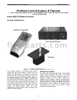
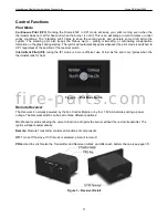
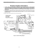
Receiver
The Receiver accepts commands via radio frequency
from the Remote to operate the appliance. The
Receiver is powered (6V DC) by the Fan Control
Module and uses four 1.5 volt AA type batteries for
backup during power outages. The Receiver
’s slider
switch is set to one of three positions: ON (Manual
Override), REMOTE (Remote Control) or OFF. The
ON selection turns the valve on (to high) if the
Remote becomes inoperative.
Fan Control Module
The Fan Control Module (FCM) is the main power
supply for the entire system when 120v AC is
available. The FCM is part of the blower assembly
(packaged separately). The FCM provides two 120V
remotely controlled outlets, and one constantly
powered outlet. The FCM allows the remote to
control the fan unit through 6 speeds and turns the
auxiliary outlet on and off. This module also powers
the Receiver and Ignition Module with 6v DC, making
the batteries in the Receiver a backup power source
expanding the life of the batteries. When 120V power
is not available the FCM will not operate.
The FCM is equipped with a three-prong (grounding)
plug for protection against shock hazard and should
be plugged directly into a properly grounded three-
prong receptacle. Do not cut or remove the grounding
prong from the plug.
Proflame DFC Ignition Module
This is the command center for the appliance. The
DFC Module allows the pilot to run in the Intermittent
(IPI) mode or the Constant (CPI) mode. It signals the
burner to light or shut down and provides the ignitor
with the electricity needed for sparking. The DFC
Module is powered by the FCM when 120V power is
available or by the batteries in the Receiver during a
power outage.
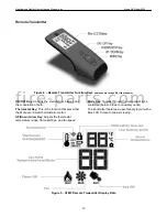
SIT Modulating Gas Valve
The remote transmitter can modulate the valve and
the flame to 6 different settings between high and
low. You can modulate the flame via the remote
yourself or by setting the remote control to the Smart
Thermostat modulation mode. Smart mode means
that as the room temperature approaches the limit set
for shut down the valve will automatically gradually
step down the flame height. The reverse happens
when the room cools - the valve will automatically
gradually increase the flame height.
Pilot Assembly
The pilot assembly consists of a pilot hood, sensor
rod, and ignitor. The ignitor sends a spark to the pilot
hood which ignites the gas and lights the pilot. With
the pilot lit the sensor rod is engulfed by the flame,
flame rectification occurs and the appliance remains
lit. If the sensor does not stay engulfed by the flame
the main burner will not light and the pilot will shut
down.
f i r e - p a r t s . c o m

