background image

HearthStone Quality Home Heating Products Inc

                                                                   Tucson 

Model #8700


21

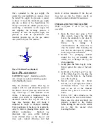
Once connected to the gas supply, the 
supply line and manifold gas pressures must 
be tested. The supply line pressure is tested, 
to insure it meets the minimum gas supply 
pressure as listed in the Specifications for 
the type of fuel in use (natural gas or LP), by 
connecting a manometer to the supply line 
and adjusting the incoming pressure if 
necessary to meet the required supply line 
pressure as listed in specifications. The 
manifold pressure tap on the gas control 
valve, refer to Figure 9 for location. 
 

3" MIN.

Cap

Nipple

To Equipment

Inlet

Tee Fitting

Gas Supply

Inlet


Figure 10 Sediment Trap (Required) 

L

OG 

P

LACEMENT


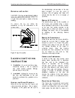
CAUTION:

 Fragile!   Handle log set with 

care. Always wear gloves and safety goggles 
while handling the log set. 
 
Only the decorative ceramic fiber log set 
supplied with the unit should be placed in 
the firebox. Do not place any other ceramic 
logs, wood logs, or other materials in the 
firebox.  If the log set is damaged or broken 
contact your dealer for replacement.  The 
decorative ceramic fiber log set will last a 
long time, however, they will break if 
subjected to rough or improper handling. 
Exact positioning of the log set is required in 
order to obtain a pleasing flame pattern and 
efficient combustion.  Incorrect log 
placement may cause carbon build-up; 
excess thermal stress on the log set and 
stove parts, reduced efficiency, and high 

levels of carbon monoxide. If the log set 
does not set into the firebox exactly as 
outlined, contact your dealer for assistance. 

 
I

NSTALLATION OF THE 

L

OG 

S

ET


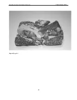
(Refer to figures 11 & 12 for log set 
assembly) 


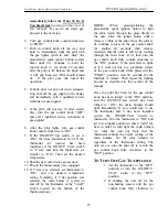
1.  Open the front door using a 5/32 

allen wrench. Loosen the bolt that 
fastens the doorknob to the door. It 
also unfastens the door from the 
firebox by turning it 
counterclockwise. Be careful not to 
chip the enamel when loosening the 
bolt. Pull the door open by grabbing 
the top edge of the door frame. 

2.  Remove the packaging material 

around the log set assembly. Be 
careful not to damage the log set 
when unpacking. 

3.  Gently place the Main Log (1) in the 

firebox against the center of the back 
wall. 

4.  Gently place the Top Log (2) on top 

of the Main Log (1), inserting the 
posts into the holes in  the bottom 
side of the Top Twig. 

5.  Spread evenly across the Ember 

Screens, one layer high, the 2 ounces 
of Charcoal Embers . You will not 
need to use all of the Charcoal 
Embers. Keep the rest to use in the 
future. 

6.  With a 5/32” allen wrench, use the 

bolt to fasten the door to the firebox. 
Make sure the door and knob are 
properly secured to the firebox 
before turning the unit on. Be careful 
not to chip the enamel when 
fastening the door. 

Summary of Contents for Tucson (8700)

Page 1: ...fire department A qualified installer service agency or gas supplier must perform installation and service AVERTISSEMENT Assurez vous de bien suivre les instructions donn dans cette notice pour r dui...

Page 2: ...ims if necessary Keep your original receipt in a safe place as proof of purchase Serial Number Fuel type check one Natural Gas Liquid Propane Sold by Phone Date of Purchase Installed by Phone Date of...

Page 3: ...the optional thermostat has been installed and the On Off T stat switch is set to T stat the wall mounted thermostat will control the on off cycling of the unit At any time you can override the therm...

Page 4: ...o smoke turn the heater off and call a qualified service technician The appliance and its individual shutoff valve must be disconnected from the gas supply piping system during any pressure testing of...

Page 5: ...the accumulation of dust and lint NEVER BURN PAPER WOOD OR OTHER MATERIALS This gas heater is designed to burn natural gas or liquid propane LP Never burn any fuel not intended for use with this unit...

Page 6: ...by using a piezoelectric spark generator as described elsewhere in this manual Never attempt to light the pilot or main burners by hand with a match or lighter If after repeated attempts the pilot li...

Page 7: ...qu s sur la plaque signal tique Ne pas l utiliser avec d autres gas sauf si un kited conversion certifi est install SERVICE CAUTION Any shield door or safety screen component removed for servicing wil...

Page 8: ...21 88 2002 CSA 2 33 M02 CAN CGA2 17 M91 Certified for Canada Approved for Mobile Home Installation see page 7 Figure 1 Tucson Dimensions NG LP Input rating Btu hr 0 1370 m 26 000 26 000 Maximum output...

Page 9: ...When putting the unit back into service follow the lighting instructions described on page 24 When the unit is first lit especially when cool it is normal to experience some condensation on the inside...

Page 10: ...ng the thermostat to OFF and turning off the gas control valve Allow the unit to cool Check and clean any burner ports that are not burning or not burning properly Clean burner ports using soft a soft...

Page 11: ...nd mark the spot to be cut 4 Cut the gasket at the marked spot with a utility knife Twist the ends slightly to prevent the gasket from unraveling 5 Apply water glass adhesive to the gasket channel 6 S...

Page 12: ...ufactured Home Installation ANSI NCBCS A225 1 or Standard for Gas Equipped Recreational Vehicles and mobile Housing CSA Z240 4 CAN SCA Z240 MH Canada Installer l appareil selon les codes ou r glements...

Page 13: ...f visible or concealed damage is found or suspected contact your dealer for instructions With the top grill removed and set aside undo the lag bolts that fasten the unit to the pallet Take care not to...

Page 14: ...r to Figures 6 7 depending on whether the installation calls for vertical rise within the room or a rear exit through the wall vent pipe Be sure to consider the need for access to the gas control valv...

Page 15: ...roperly connected to a 4 102 mm diameter type B 1 vent which is constructed and installed in accordance with NFPA54 and NFPA211 Single wall vent pipe may be used within the same room as the Tucson so...

Page 16: ...t The Tucson cannot and must not be connected to an outside air source the unit must take its combustion air from the living space in which it is installed The draft hood is equipped with a safety shu...

Page 17: ...devices prevents operation of the heater unless the power vent is operating properly Both the Tucson and the power vent are controlled by the wall thermostat and neither will operate if there is a pow...

Page 18: ...nd away from any influences that may cause the temperature in the vicinity of the thermostat to be unrepresentative of the room temperature in general Such influences might include strong lighting a h...

Page 19: ...servicing Attention Au moment de l entretien des commandes tiquetez tous les fils avant le d branchement Des erreurs de c blage peuvent entra un fonctionnement inadequate et dangereux The proper loca...

Page 20: ...gas control valve just inside the left front leg of the unit using a 3 8 male NPT fitting The supply line should be diameter or appropriately sized to provide a sufficient gas supply to meet the maxi...

Page 21: ...in order to obtain a pleasing flame pattern and efficient combustion Incorrect log placement may cause carbon build up excess thermal stress on the log set and stove parts reduced efficiency and high...

Page 22: ...HearthStone Quality Home Heating Products Inc Tucson Model 8700 22 Figure ll Log Set...

Page 23: ...water based polishing system prior to the assembly of the unit Any residue moisture in the stones must be dried out slowly to avoid damaging the stones This is accomplished by adhering to the followi...

Page 24: ...And Gas Supply and Connections sections of this manual the unit is almost ready to be lit for the first time The manufacturer tests each unit prior to shipment so ignition should take place without fa...

Page 25: ...e thermostat or the on off switch located on the bottom of the thermostat body NOTE When pressing clicking the piezoelectric spark ignition button to light the pilot watch through the glass front of t...

Page 26: ...if the burner flame needs adjustment it is necessary to view the flame pattern with the variable output control knob at its highest setting turn fully clockwise Allow the unit to operate for 10 minut...

Page 27: ...erature and for the flame pattern to stabilize Generally the more air open shutter in the mixture the bluer the flame Less air closed shutter results in a more yellow flame but too little air will res...

Page 28: ...et 93 56201 LP Conversion Kit 5710 180 Door Latch Bracket 7200 240 Burner Orifice NG 40 2710 560 Glass Ret Frame 7200 253 Burner Orifice LP 53 2710 581 Front Grill 7211 370 Pilot Burner Assembly 2710...

Page 29: ...insulation If properly connected and no spark replace ignitor E Clean or replace the pilot assembly 2 Pilot will not stay lit after carefully following lighting instructions A Low or too high gas pre...

Page 30: ...er does not come on replace the gas valve C Remove and check burner orifice clean or replace Note do not use any metal cleaning device as this may damage the orifice 4 Pilot and burner come on but go...

Page 31: ...B2 Clear obstructions B3 Clear obstructions C If gas pressures are correct and the flames stay the same adjust the air shutter for a proper burn 9 Burner flashback Air gas mixture ignites inside the b...

Page 32: ...box and firebox baffle against breakage cracking or burn through Convective heat exchanger against breakage cracking or burn through Burners air shutters and orifices against breakage cracking or burn...

Page 33: ...OR REMEDIES IN CONTRACT OR TORT WHETHER OR NOT ARISING FROM HEARTHSTONE S NEGLIGENCE ACTUAL OR IMPUTED ALL IMPLIED WARRANTIES INCLUDING THE WARRANTIES OF MERCHANTABILITY AND FITNESS FOR A PARTICULAR...

Page 34: ...r parts Within the first ninety 90 days after the Purchase Date HearthStone will pay for the shipping of Stove parts covered by any of the foregoing warranties to and from HearthStone or a Dealer as t...

Reviews: