background image

OWNER’S MANUAL                                                                                  MODEL:  8745 TUCSON Vent-Free HEATER


-11- 

 
ELECTRICAL CONNECTIONS 

NOTE:

 OPEN VALVE DOOR UNDER ASH LIP 

FOR ELECTRICAL AND GAS CONNECTIONS 

 
Thermostat


The Tucson may use the wall mounted thermostat for 
operation, or the on/off/tstat switch. The thermostat 
controls the unit by “calling for heat.”  The 
thermostat turns the unit on when the room is cold, 
and turns the unit off once the room is warmed 
sufficiently. The thermostat is controlled by a 750 
millivolt DC two-wire circuit. Both the thermostat 
and 40'  of thermostat wire are included as standard 
equipment. 


Thermostat Placement


The thermostat should be placed in the same room or 
living space as the unit.  Typically 5'  off the floor 
and away from any influences that may cause the 
temperature in the vicinity of the thermostat to be 
unrepresentative of the room temperature in general. 
Such influences might include strong lighting, a 
heater vent from the central heating system, or a 
nearby drafty window. 


Placement of the thermostat on an inside wall rather 
than an outside wall is preferable. Do not  place the 
thermostat directly behind or too close to the unit, 
otherwise heat from the unit will immediately satisfy 
the thermostat and turn the unit off. 

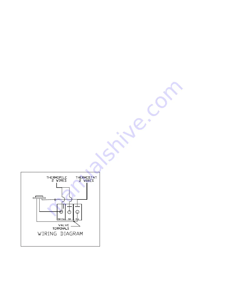
Violet

Black

Yellow

On/Off/T-stat


Figure 4 Wiring diagram 

 
Thermostat Wiring


The thermostat wire from the unit to the thermostat 
can be surface mounted, routed under the floor, or 
through walls, etc. The thermostat should be 
connected to the unit using the 40' , or as much as 
needed, of insulated thermostat wire provided. Be 
sure to leave a small coil of wire behind the unit so 
that it can be moved out of position for servicing and 
cleaning. 
 
The proper location of wire connections is shown 
below and in Figure 10.  When making these 
connections, position the thermostat wire so  it 
extends towards the wall behind the unit, then 
towards the thermostat.  (At the thermostat, the wires 
should be connected to the two connection screws on 
the back of the thermostat per the instructions 
received with the thermostat). Take care not to over-
tighten the connection screws and not to damage the 
internal parts of the thermostat.  Now attach the wires 
in their  proper location, shown in Figure 10. 


Location of Wire Connections:


WIRE 


   LOCATION 


LABEL


Thermostat(2 wires)  1- Top Post on Valve     TH 


1- On/Off/T-stat switch Yellow wire 

Thermopile(2 wires) 

1- Bottom Post  


   TP/TH 


1- Middle Post  


   TP 


Summary of Contents for TUCSON 8745

Page 1: ...erformed by a qualified installer service agency or the gas supplier This is an un vented gas fired heater It uses air oxygen from the room in which it is installed Provisions for adequate combustion...

Page 2: ...___ __________________________________ ____ _________________ _______________ __________________________________ ____ _________________ _______________ __________________________________ ____ ________...

Page 3: ...he heat output along with the flame height to suit personal needs Heat output can be reduced during the Fall and Spring when the need for heat is reduced and increased during Winter months when the ne...

Page 4: ...ill be operating The installation must conform with local codes or in the absences of local codes the current National Fuel Gas Code ANSI Z223 1 NFPA 54 DO NOT INSTALL THIS HEATER IN A BEDROOM OR BATH...

Page 5: ...tric spark generator as described in the How To Turn the Unit On Off section of this manual Never attempt to light the pilot or main burners by hand with a match or lighter After repeated attempts if...

Page 6: ...stibles Minimum alcove height 22 above stove top HEARTH REQUIREMENTS FLOOR PROTECTION The Tucson can be installed on wood flooring or a non combustible surface For installation of the Tucson on carpet...

Page 7: ...s to be installed meets the following criteria it is considered to be an unconfined space The room in which the heater is to be installed has an air volume of at least 50 cubic feet cubic feet length...

Page 8: ...f the number from III is smaller than the number calculated in II the space should be considered an unconfined space If the number from III is larger than II the space should be considered a confined...

Page 9: ...d space needs to have two permanent openings one commencing within 12 inches 30 cm of the top and one commencing within 12 inches 30 cm of the bottom of the enclosure The openings shall communicate fr...

Page 10: ...the top three stones and grill Use the protective wrapping material to temporarily protect the stones from chipping or damage while the unit is inspected and installed With the top stones and grill r...

Page 11: ...ly behind or too close to the unit otherwise heat from the unit will immediately satisfy the thermostat and turn the unit off Violet Black Yellow On Off T stat Figure 4 Wiring diagram Thermostat Wirin...

Page 12: ...line should be diameter or appropriately sized to provide a sufficient gas supply to meet the maximum demand of the unit without undue loss of pressure We recommend a flexible line to avoid undue mec...

Page 13: ...use however they will break if subjected to rough or improper handling Broken or cracked logs should be replaced When removing and replacing the log set from the unit during routine cleaning or servic...

Page 14: ...m the firebox The log set assembly will be in four pieces along with the charcoal embers as shown in Figure 6 First remove the Top Log 6 by pulling it up off the Middle Log 2 and out of the firebox Ne...

Page 15: ...o its lowest setting or OFF position If the gas control knob is not in the OFF position turn the knob fully clockwise to OFF Locate the variable output and turn it fully clockwise to the highest setti...

Page 16: ...en turned to the ON position the main burners are lit by selecting ON of the On Off T stat switch or if T STAT was selected by moving the thermostat to a high setting so that it calls for heat i e tur...

Page 17: ...ly the thermocouple as well located next to the pilot but not so large as to create excessive noise or consume excessive gas However it can be adjusted by means of the pilot light adjustment screw loc...

Page 18: ...accumulation of dust lint and other debris To clean the firebox set the thermostat to the OFF position and turn off the gas at the gas control valve When the unit is cool u nfasten the front door and...

Page 19: ...x 6 1741 352 top center stone 8e x 3e 7211 554 rear log 7211 559 middle log 7211 556 front log 7211 557 top log 7211 558 charcoal ember 2 oz 5320 070 ember screen 5710 119 light shield 5710 120 back l...

Page 20: ...TER 20 Natural Gas LP Input rating Btu hr 20 000 20 000 Minimum input rating Btu hr 13 500 16 000 Orifice size DMS 44 55 Man pressure HI setting in w c kPa 3 5 10 0 Man Pressure Lo setting in w c kPa...

Page 21: ...oltage between valve body and solder connection on the rear of the valve where the blue wire connects It should be no less than 7mV C1 Ensure that the thermocouple connection at the gas valve is tight...

Page 22: ...input underrated C Valve leak if flashback occurs with burner valve in off position D Improper gas pipe size A Incorrect air to fuel ratio A1 Primary air incorrect A2 Burner ports plugged B Pilot not...

Page 23: ...d orifices against breakage cracking or burn through Ceramic logs and embers against breakage cracking or burn through This warranty expires on the fifth 5th anniversary of the Purchase Date LIMITED T...

Page 24: ...RRANTIES OF MERCHANTABILITY OR FITNESS FOR A PARTICULAR PURPOSE SHALL APPLY TO THE SUBJECT STOVE SOME STATES DO NOT ALLOW LIMITATIONS ON HOW LONG AN IMPLIED WARRANTY LASTS SO THE ABOVE LIMITATION MAY...

Page 25: ...ts related to shipping Stove parts to and from HearthStone or a Dealer as the case may be Shipping cost for the Stove Within the first 1st year after the Purchase Date if the Original Purchaser is ins...

Reviews: