OWNER’S MANUAL MODEL: 8745 TUCSON Vent-Free HEATER
-12-
GAS SUPPLY & CONNECTIONS
Gas Supply
NOTICE: A qualified technician must connect the
heater to the gas supply and leak test the unit
before it is approved for use. Consult all local
codes.
WARNING:
The unit must be installed and
connected in accordance with local codes, or in the
absence of local codes, with the most current edition
of the National Fuel Gas Code ANSI Z223.1/NFPA
54.
We recommend using new black iron or steel pipe
only. Internally tinned copper tubing can be used in
some areas when permitted by local codes. Only use
pipe of ½" or greater diameter to allow full gas
volume to heater. Excessive pressure loss will occur
if the pipe is too small.
The supply line must include a manual shut-off valve
and union so that the unit can be disconnected for
servicing Also a sediment trap must be installed
upstream of the heater. The sediment trap is installed
to prevent moisture and contaminants from passing
through the pipe to the heater controls and burners.
Failure to install a sediment trap could prevent the
heater from operating reliably.
The gas supply line connection is made to the
Tucson’s gas control valve just inside the left front
leg of the unit using a
d
" male NPT fitting. The
supply line should be ½" diameter or appropriately
sized to provide a sufficient gas supply to meet the
maximum demand of
the unit without undue loss of pressure. We
recommend a flexible line to avoid undue mechanical
load on the valve and to ease thread alignment, but
also refer to local code.
CAUTION: Check Gas Type!
The gas supply must
be the same as stated on the heater’s rating
plate(located on the back of the unit). If the gas
supply is different,
DO NOT INSTALL
the heater.
Contact your dealer for the correct model.
Gas Pressure Adjustment
The supply line pressure is tested, to ensure it meets
the minimum pressure, as listed in the Specifications
sections of this manual, for the type of fuel in use
(NG or LP). The Tucson must be isolated from the
gas supply piping system by closing its individual
manual shutoff valve during any pressure testing of
the gas supply piping system at test pressures equal to
or less than ½" psig. During tests in excess of ½"
psig. (14" w.c.), the heater must be disconnected from
the gas supply system. Test by connecting a
manometer to the supply line. Adjust the incoming
pressure, if necessary, to meet the required supply
line pressure. Once connected to the gas supply, the
gas inlet pressure and manifold gas pressure must be
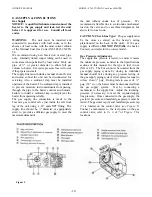
tested. The gas inlet tap (6) and manifold pressure tap
(7) is located on the control valve (
see Figure 5
).
Connect a manometer to the test points on the gas
control valve, refer to
#’s 6 & 7
of
Figure 5
for
locations.
Figure 5

