Hearthstone Quality Home Heating Products, Inc.
Tudor Model #8120
V
ENTING
I
NFORMATION
V
ENT
C
ONNECTION
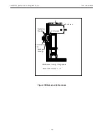
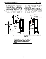
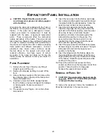
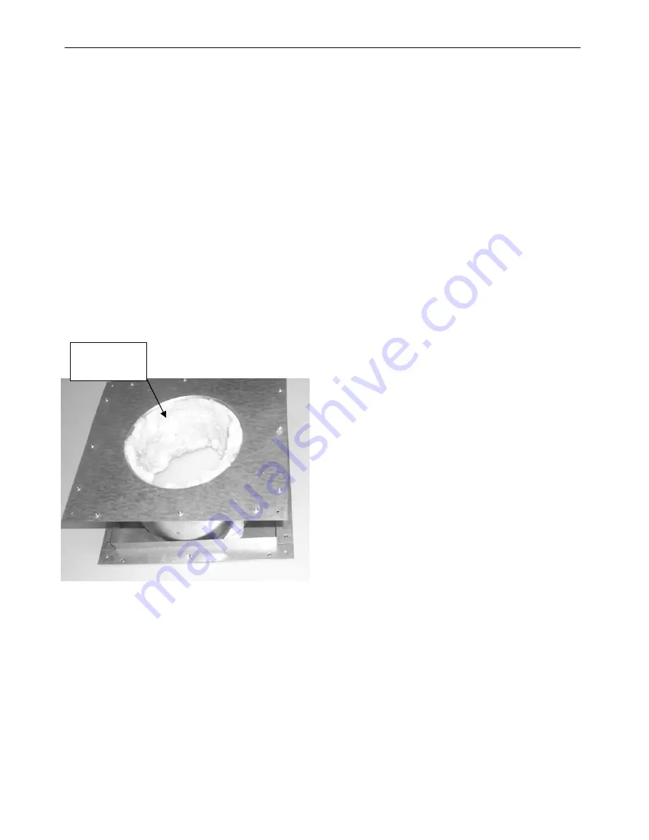
1. An insulation blanket is provided and must be
added to any wall pass through (thimble) kit.
This blanket is installed inside the wall pass
through the thimble and wraps around the pipe
that protrudes through the wall. (
see figure 5)
The blanket must extend the full-length, front to
back, of the thimble.
2. The Tudor Direct Vent is approved for
installation only with the vent connecting
components listed; Simpson Dura-Vent Direct
Vent GS, AmeriVent Direct, Selkirk Direct
Temp™ or Secure Vent systems. Use the
following instructions along with the pipe
manufacturer’s instructions to complete the
installation.
3. Install the vent system according to the
manufacturer’s instructions.
Figure 5: Wall thimble with insulation blanket
R
ESTRICTION
P
LATE
There is a vent restriction plate that regulates the
flow rate of exhaust gases. This ensures proper
flame characteristics and efficiency for the wide
variety of vent configurations available. Controlling
the draft also changes the aesthetics of the flame.
The restriction plate consists of a rotating shutter
behind the starter section of pipe and an adjustment
plate with an index hole used to hold the shutter in a
fixed position. The restriction plate has unlimited
settings. Depending on the vent configuration, you
may be required to adjust the restriction plate
position.
For horizontal, direct rear vent
installations no adjustment to the restrictor is
necessary.
R
ESTRICTION
P
LATE
A
DJUSTMENT
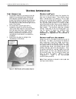
Ensure the unit is cool before touching any part of
the firebox. To adjust your restrictor for maximum
flame appearance, loosen the Phillips head screw,
found on the upper rear right side of the stove. Spin
the indicator tab into the desired position. Rotating
counterclockwise closes the exhaust gasses, while
rotating clockwise opens the exhaust gases. Once
the desired restriction is reached, tighten the screw
(Refer to figure 6).
There are unlimited positions for
the restriction plate, one (1) being the lowest and
three (3) being the highest. (Refer to Venting
Configuration – Figure 6 for recommended
restriction plate positions)
Insulation
blanket
Note:
These positions are based on lab results and
can have some variance.
12


