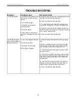
Hearthstone Quality Home Heating Products, Inc.
Tudor Model #8120
G
AS
S
UPPLY
&
C
ONNECTIONS
WARNING: THE UNIT MUST BE INSTALLED AND
CONNECTED IN ACCORDANCE WITH LOCAL
CODES, OR IN THE ABSENCE OF LOCAL CODES,
WITH THE MOST CURRENT EDITION OF THE
NATIONAL FUEL GAS CODE ANSI Z223.1 (NFPA
54) OR CAN/CGA B149 INSTALLATION CODE.
NOTICE: A qualified technician must connect
the heater to the gas supply and leak test the
unit before it is approved for use. Consult all
codes.
NFPA Code, and Hearthstone require the use of
a dedicated sediment trap just upstream of the
unit. Damage to the valve, or other components
due to the lack of a sediment trap are not
covered by warranty.
3" MIN.
Cap
Nipple
To Equipment
Inlet
Tee Fitting
Gas Supply
Inlet
Figure 11: Typical Sediment Trap (Required in all
installations)
G
AS
C
ONNECTIONS
The gas supply connection is made to the Tudor’s
gas control valve in the middle of the lower rear of
the stove, using a 3/8” male NPT fitting. The supply
line should be ½” diameter, or appropriately sized to
provide a sufficient gas supply to meet the maximum
demand of the unit without undue loss of pressure.
We recommend a flexible line to avoid undue
mechanical load on the valve and to ease thread
alignment, but refer to local codes.
CAUTION: CHECK GAS TYPE!
G
AS
S
UPPLY
This appliance and its individual shutoff valve must
be disconnected from the gas supply piping system
during any pressure testing of that system at test
pressures in excess of ½ psig. The Tudor must be
isolated from the gas supply piping system by
closing its individual manual shutoff valve during any
pressure testing of the gas supply piping system at
test pressures equal to or greater than ½ psig.
G
AS
P
RESSURE
A
DJUSTMENT
NOTE: A QUALIFIED TECHNICIAN MUST
PERFORM THIS PROCEDURE!
Once connected to the gas supply, the supply line
and manifold gas pressures must be tested. The
supply line pressure is tested, to insure it meets the
minimum gas supply pressure as listed in the
Specifications for the type of fuel in use (natural gas
or LP), by connecting a manometer to the supply
line and adjusting the incoming pressure if
necessary to meet the required supply line pressure
as listed in specifications. The manifold pressure tap
on the gas control valve, refer to
Figure 10
for
location.
19

