Hearthstone Quality Home Heating Products, Inc.
WAITSFIELD Model 8770
20
•
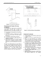
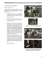
While keeping pressure on the cables and
plastic insert, tighten the thermocouple 1/4 to 1/2
turn beyond finger tight (2...3 Nm).
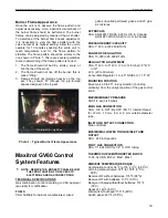
Ignition Cable
Do NOT damage the ignition cable. When the cable
is in place, avoid contact with sharp objects or
edges. Avoid contact with metal parts, as this could
decrease spark.
Receiver
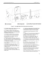
1. Insert batteries.
2. Place ON/OFF switch on valve to ON position.
Remote
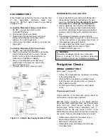
1. The receiver has to learn the handset code:
Press and hold the receiver's reset button (
Figure
41
, page 30) until you hear two (2) beeps. After
the second, longer beep, release the reset
button. Within the subsequent 20 seconds press
the small flame button on the handset until you
hear two (2) short beeps confirming the code is
set.
NOTE: This is a one-time setting only, and It is not
required when changing the batteries in the hand set
or receiver.
2. Check reception. For better reception straighten
the antenna and move it to a position that allows
for better line of sight (see notice below).
3. When the RF receiver is placed in the appliance,
the surrounding metal can reduce reception
considerably. The position of the antenna on the
receiver also influences reception.
NOTICE: The antenna must not cross or come into
contact with the ignition wire. This will
render the receiver inoperable.
WARNING
ELECTRIC SHOCK HAZARD.
Read these instructions carefully. Failure to
follow them could result in property damage,
personal injury, or loss of life.
This control must be electrically wired and
operated in accordance with all codes and local
regulations. Service and installation must be
performed by a trained, experienced service
technician.
Do NOT-use the module if you suspect it may be
damaged.
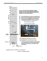
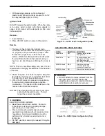
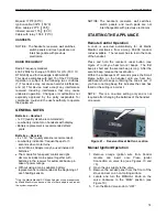
Figure 15
– GV60 Valve Configuration (Side)
GAS CONTROL KNOB SETTINGS
KNOB
POSITION
FUNCTION
Main Valve
OFF
Prevents main gas flow
through valve.
Main Valve
ON
Permits main gas flow
through valve if the pilot is lit
and thermocouple is
generating sufficient power.
MANUAL knob
MAN
Allows the pilot to be
manually ignited and
prevents main gas flow.
MANUAL knob
ON
Allows for automatic ignition.
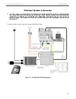
WARNING
Do NOT attempt to remove screws from the
top of gas valve. Do NOT change any
adjustments marked with tamper indicating
paint. Motor knob is not to be removed.
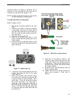
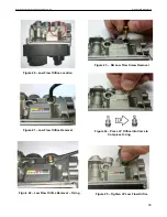
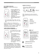
Figure 16
– GV60 Valve Configuration (Top)

