Hearthstone Quality Home Heating Products, Inc.
WAITSFIELD Model 8770
30
Burner Flame Appearance
Once the unit is lit, observe the flame pattern and
adjust as necessary. Also, a periodic visual check of
the burner flame should be performed. The burner
flames can be adjusted by means of the air shutter.
To determine if the burner flame needs adjustment,
it is necessary to view the flame pattern with the
valve output at its highest setting. Allow the unit to
operate for 10 minutes enabling the entire unit to
reach temperature and for the flame pattern to
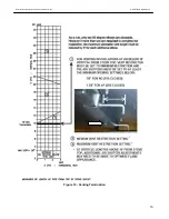
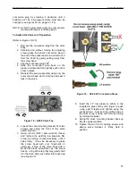
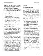
stabilize. The flame pattern should be similar to the
one shown in Photo 1. There are several guidelines
to aid in determining if the flame pattern is correct:
1. The flame should not be dirty, smoky, sooty, or
lick the top of the stove.
2. The flame should not rise off the burner; this is
called “lifting”.
3. Flames should not impinge heavily on the log
set. They should “fit” through the pre
-formed
spaces designed in the log set.
Photo 1
– Typical Burner Flame Appearance
Maxitrol GV60 Control
System Features
NOTE: REMOVE THE MODESTY PANEL BELOW
THE FRONT CASTING FOR ACCESS TO
ELECTRICAL AND GAS CONNECTIONS.
TECHNICAL SPECIFICATIONS
Gas combination control according to CSA approval
(see label for certification)
FUELS
CSA: Suitable for natural, manufactured, mixed
gases, liquefied petroleum gases, and LP gas-
air mixtures.
APPROVALS
CSA: ANSI Z21.78/CSA 6.20 for U.S. & Canada,
ANSI Z21.20/CSA 6.20 for U.S. & Canada
PRESSURE DROP/CAPACITY
CSA: 1" W.C. at 65,000 BTU/hr
RANGE OF REGULATION
CSA: 10,000 to 85,000 BTU/hr
REGULATOR ADJUSTMENT
CSA: 3" W.C. to 5" W.C. (7.5 to 12.5 mbar); 8" W.C.
to 12"
W.C. (20 to 30 mbar)
Convertible Regulator: 3 to 4.5" NG/8.5 to 11.5" LP
MOUNTING POSITION
Mount valve 0 to 90
0
, in any direction (including
vertically) from the upright position of the gas control
knob.
MAXIMUM INLET PRESSURE
CSA:1/2 psi (3.45 mbar)
MAIN GAS CONNECTION
CSA: 3/8” in, NPT; Rp3/78”
ISO 7-1 internal thread
for 12 mm, 10 mm, 8 mm, 6 mm outside diameter
tube.
INLET AND OUTLET CONNECTION
Side or Bottom
MAXIMUM ALLOWED TORQUE INLET AND
OUTLET
CSA: .280 inch-pounds
PILOT GAS CONNECTION
CSA: 7/16-24 UNS for 1/4" or 3/16" tubing
THERMOCOUPLE/INTERRUPTER BLOCK
11/32-32 UNS, M10x1, M9x1, M8x1
AMBIENT TEMPERATURE RANGE
Combination control: 32
o
F to 176
o
F (0
o
C to 80
o
C)
Latching solenoid valve: 32
o
F to 176
o
F (0
o
C
to
80
o
C)
Receiver RF without batteries: 176
O
F (80
o
C)
Receiver RF with batteries: 131
o
F (55°C)
Receiver infrared with/without batteries: 131
o
F
(55
o
C)
Handset: 140
o
F (60°C)
Wall switch/Touchpad: 176
O
F (80°C)
Switch panel: 221
o
F (105°C)
aitsfield D – igh urn

